
Microexplosion device for destructing electronic chips

An electronic chip and micro-explosion technology, which is applied in the field of electronic chip safety protection, can solve the problem of not designing an electronic chip device, and achieve the effects of good versatility, good environmental adaptability, and small size

Pending Publication Date: 2020-07-10
南京瑞浦景科技有限公司
View PDF1 Cites 4 Cited by
  • Summary
  • Abstract
  • Description
  • Claims
  • Application Information

AI Technical Summary

Problems solved by technology

However, this patent only proposes a conceptual method for physical damage to chips, and does not design a specific device for physical destruction of electronic chips

Method used


Image

  • Microexplosion device for destructing electronic chips
  • Microexplosion device for destructing electronic chips
  • Microexplosion device for destructing electronic chips

Examples


Embodiment Construction

[0026] The specific embodiments of the present invention will be further described below in conjunction with the accompanying drawings.

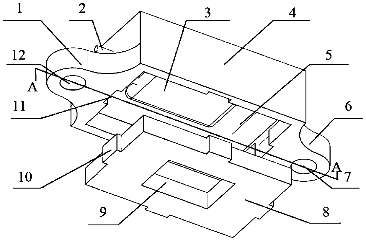
[0027] to combine Figure 1 to Figure 6 , the present invention is a micro-explosion device for electronic chip destruction, comprising an upper casing 4, a detonating detonator 3, a pyrotechnic product chamber 5 and a lower guard plate 8;

[0028] The upper casing 4 and the lower guard plate 8 form a sealed space, and the detonating detonator 3 and the pyrotechnics chamber 5 are arranged in the sealed space; the lower guard plate 8 is provided with an explosion directional window 9, and an explosion directional window 9 Located in the center of the lower guard plate 8.

[0029] Further, the upper casing 4 and the lower guard plate 8 are fixed by mortise and tenon or screw.

[0030] As a specific example, the mortise and tenon fixing method is as follows:

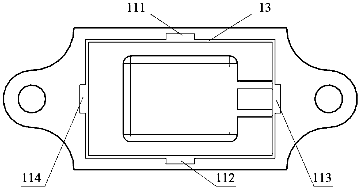
[0031] to combine image 3 , the hollow body of the opening below the upper casin...


PUM


Abstract

The invention discloses a microexplosion device for destructing electronic chips. The microexplosion device comprises an upper housing, a blasting cap, an initiating explosive device chamber and a lower protection plate, wherein the upper housing is an empty cavity with an opening in the lower part; fixed supporting ears are arranged at two ends of the outer part of the upper housing; the blastingcap has two blasting signal lines, and the two blasting signal lines are led out from the side wall of the upper housing; high explosive is stuffed to the upper part of the initiating explosive device chamber, and insulating materials are stuffed to the lower part of the initiating explosive device; an explosion orienting window is arranged on the lower protection plate; an energy attenuation plate is arranged in the explosion orienting window; and a plurality of controlled fragments are arranged on the energy attenuation plate. The microexplosion device for destructing electronic chips disclosed by the invention is controllable in explosion opportunity and explosion power, small in size, long in storage time, good in environmental compatibility, and convenient to load and unload; an assigned electronic chip can be effectively and physically damaged; and besides, through the energy attenuation plate, the explosion power is controlled, so that other electronic components are not damaged, the purpose that under a certain condition, the assigned electronic chip is destructed is achieved, and the data security of the electronic chip is improved.

Description

technical field [0001] The invention relates to the technical field of electronic chip safety protection, in particular to a micro-explosion device used for destroying electronic chips. Background technique [0002] With the development of science and technology, the functions of electronic chips are becoming more and more powerful. Chips with storage and control functions have become an important carrier of technology and information. In some cases, these chips with storage and control functions need to be destroyed. The destruction of electronic chips is mostly the method of circuit fusing, and the key electronic chips are not destroyed in essence, and can be restored under certain conditions. [0003] In order to completely destroy the information stored in the electronic chip, the only way is to physically destroy the chip wafer. Human-made physical damage is easily disturbed by various factors, resulting in the chip being unable to be destroyed. Therefore, a chip-level ...

Claims


Application Information

Patent Timeline
Patent Type & Authority Applications(China)
IPC IPC(8): B09B3/00B09B5/00
CPCB09B3/00B09B5/00Y02W30/82
Inventor 孙万忠韩学平周明春刘静
Owner 南京瑞浦景科技有限公司
Learn More