Clamping mechanical arm with self-adjusting clamping force

A self-adjusting, manipulator technology, which is applied in the field of manipulators, can solve the problems of inconvenient and precise clamping, use of occupied space, increase in volume, etc., and achieve the effect of simplified structure, large clamping range and simple structure

Active Publication Date: 2020-07-10
数源汇通(北京)医药科技有限公司
View PDF6 Cites 17 Cited by
  • Summary
  • Abstract
  • Description
  • Claims
  • Application Information

AI Technical Summary

Problems solved by technology

[0002] Industrial manipulator is a high-tech automatic production equipment developed in recent decades. The manipulator is a new type of device developed in the process of mechanization and automation. The existing manipulators are divided into linear moving clamping and shearing and rotating clamps There are two kinds of clamping devices. The linear moving clamping device is more stable in clamping and can accurately find the target, but the volume of the device increases with the increase of the clamping range, which takes up space. The shearing and rotating clamping device can flexibly adjust the clamping range. The size of the volume has little effect, but it is not convenient for precise clamping and cannot meet the actual needs. Therefore, we have invented a clamping manipulator with self-adjusting clamping force

Method used


Image

  • Clamping mechanical arm with self-adjusting clamping force
  • Clamping mechanical arm with self-adjusting clamping force
  • Clamping mechanical arm with self-adjusting clamping force

Examples


Embodiment Construction

[0014] In order to make the purpose, technical solutions and advantages of the embodiments of the present invention clearer, the technical solutions in the embodiments of the present invention will be clearly and completely described below in conjunction with the drawings in the embodiments of the present invention. Obviously, the described embodiments It is a part of embodiments of the present invention, but not all embodiments. Based on the embodiments of the present invention, all other embodiments obtained by persons of ordinary skill in the art without creative efforts fall within the protection scope of the present invention.

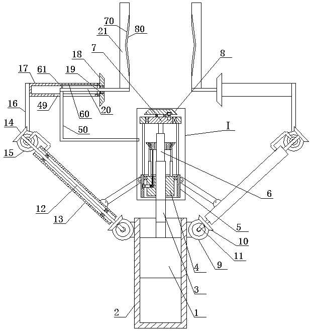
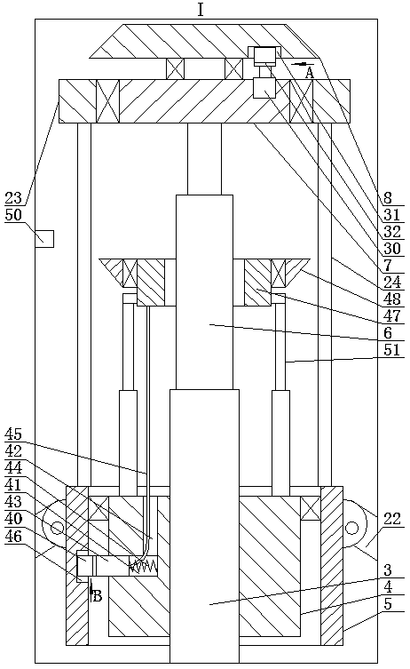
[0015] A clamping force self-adjusting clamping manipulator, as shown in the figure, includes a motor 1, the outer circumference of the motor 1 is fixedly connected to the inner circumference of the vertical pipe 2, the upper end of the motor 1 rotating shaft is fixedly connected to the lower end of the screw rod 3, and the upper end of the screw r...


PUM


Abstract

The invention discloses a clamping mechanical arm with a self-adjusting clamping force. The clamping mechanical arm comprises a motor, the inner circumference of a vertical pipe is fixedly connected to the outer circumference of the motor, the upper end of a rotating shaft of the motor is fixedly connected with the lower end of a screw rod, a screw nut is installed on the outer circumference of the screw rod in a threaded mode, a bearing of the outer circumference of the screw nut is connected with the inner circumference of a sleeve pipe, a first limiting device for limiting the rotation of the screw nut is arranged on the inner side of the sleeve pipe, the upper end of the screw rod is connected with the lower end of a telescopic shaft, the upper end of the telescopic shaft is fixedly connected to the middle of the top side of a rotating plate, a bearing of the top side of the rotating plate is connected with the bottom side of a coaxial first helical gear, and a second limiting device is arranged between the rotating plate and the first helical gear. According to the clamping mechanical arm, the structure is simple, the conception is ingenious, the linear moving clamping and theshearing moving clamping are combined, thus the advantages and disadvantages of the two clamping modes are complemented with each other, a large clamping range is retained, meanwhile the volume can be adjusted, convenient use is achieved in a narrow space, two clamping structures are driven by one motor, the structure is simpler, the production cost is saved, the market demand can be met, and theclamping mechanical arm is suitable for popularization.

Description

technical field [0001] The invention belongs to the field of manipulators, in particular to a clamping manipulator with self-adjusting clamping force. Background technique [0002] Industrial manipulator is a high-tech automatic production equipment developed in recent decades. The manipulator is a new type of device developed in the process of mechanization and automation. The existing manipulator is divided into linear moving clamping and shearing and rotating clamping. There are two kinds of clamping devices. The linear moving clamping device is more stable in clamping and can accurately find the target, but the volume of the device increases with the increase of the clamping range, which takes up space when used, while the shearing and rotating clamping device can flexibly adjust the clamping range. The size of the volume has little effect, but it is not convenient for precise clamping and cannot meet the actual needs. Therefore, we have invented a clamping manipulator w...

Claims


Application Information

Patent Timeline
Patent Type & Authority Applications(China)
IPC IPC(8): B25J15/08B25J9/12B25J9/10
CPCB25J9/10B25J9/102B25J9/12B25J15/08
Inventor 徐福云徐福新刘燕刘力莉田力平殷守彦郑丽燕李宝乐
Owner 数源汇通(北京)医药科技有限公司
Why Eureka
Try Eureka