
Dyeing nozzle and dyeing machine

A technology of nozzle and dye liquor, applied in the direction of spraying device, spraying device, spraying/jetting textile material processing, etc., can solve the problems of uneven impact force on the surface of the cloth, influence of the texture of the cloth, limited effect, etc., to improve the dyeing efficiency. and finished product quality, avoid tangling and knotting, and the effect of simple structure

Inactive Publication Date: 2020-07-10
杭州宏事晟机械科技有限公司
View PDF4 Cites 3 Cited by
  • Summary
  • Abstract
  • Description
  • Claims
  • Application Information

AI Technical Summary

Problems solved by technology

Although this solution can achieve a certain anti-crease effect, the use of distributed water flow has caused uneven impact on the surface of the fabric.
[0003] Another patent (publication number CN110258042A) titled "Dyeing Device with Long Flat Nozzle with Automatic Filtration System and Its Untangle Control Method" proposes a solution to the twisting and knotting of fabric passing through the nozzle. The solution is to design the annular nozzle into a flat shape, and then cooperate with the complex control method to play a certain role in anti-twist knotting, but the long and flat nozzle is still circular, which is only slightly flat compared to the circular one, and the effect is limited. , will still have an impact on the side of the fabric, so that creases will still occur on the side of the fabric, and because the opening of the nozzle is relatively large, the length is short, and the inner cavity of the nozzle's dyeing liquid into and out of the material tube is small, it is difficult to The same pressure at each part of the nozzle will make the liquid flow from each part of the outlet uneven, which will still cause the torsion of the fabric and uneven dyeing. In the case of low dyeing liquid pressure or pressure fluctuations, the impact will be greater , even due to the uneven impact force of the liquid flow on each part of the cloth, the structure of each part of the cloth will change unevenly, thus affecting the texture of the cloth

Method used


Image

  • Dyeing nozzle and dyeing machine
  • Dyeing nozzle and dyeing machine
  • Dyeing nozzle and dyeing machine

Examples


Embodiment 1

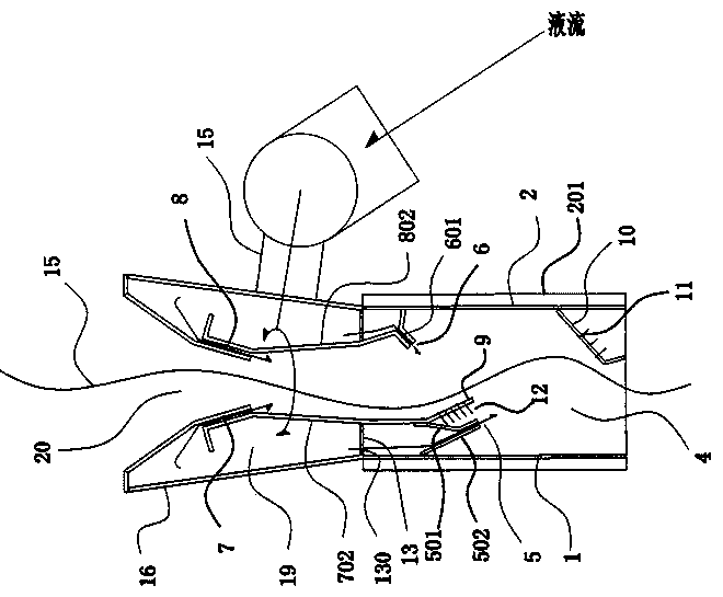
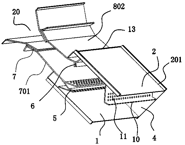
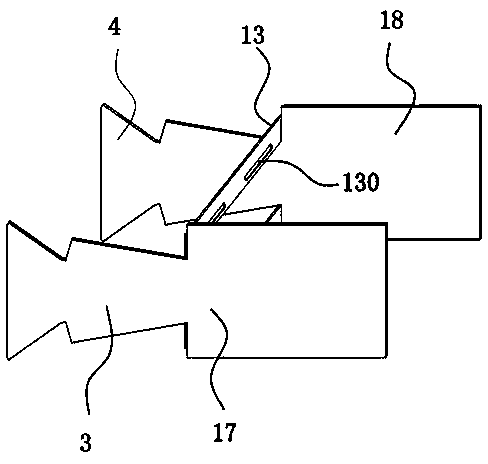
[0027] Such as figure 1 , 2 , 3, 4, and 5, the dyeing nozzle includes an inner wall and an outer wall 16, the inner wall forms a distribution channel 20, and the cross section of the distribution channel is a rectangular channel adapted to the width of the cloth. The passage has four inner wall surfaces, front, rear, upper, lower, and front. The front and rear sides are front wall panels 17 and rear wall panels 18 with the same structure. The lower dye solution outlet 7 and the upper dye solution outlet 8 facing the upper and lower sides of the cloth are respectively arranged on the upper and lower inner wall surfaces. The dyeing port is arranged obliquely in the advancing direction of the channel relative to the cloth, that is, it is inclined towards the advancing direction of the cloth, so that the liquid flow impacts the cloth and drives the cloth to advance. The lower inner wall surface includes the upper plate body 701 of the lower dye solution outlet and the lower plate...


PUM


Abstract

The invention provides a dyeing nozzle and a dyeing machine, and relates to cloth dyeing equipment. The dyeing nozzle and the dyeing machine solves the problem that in the prior art, cloth is wound and knotted. The dyeing nozzle comprise a cloth channel, a dye liquor outlet and a dye liquor inlet, wherein the section of the cloth channel is a flat channel adapting to the width of the cloth, a lower dye liquor outlet and an upper dye liquor outlet facing the upper surface and the lower surface of the cloth are formed in the inner wall of the cloth channel, a dyeing opening is obliquely formed relative to the cloth channel, the lower dye liquor outlet and the upper dye liquor outlet communicate with the same isobaric cavity, after a liquor in the isobaric cavity reaches certain pressure, thedye liquor faces the surface of the cloth from the lower dye liquor outlet and the upper dye liquor outlet, and the isobaric cavity communicates with the dye liquor inlet. According to the dyeing nozzle, the slit-shaped dye liquor outlets located in the two sides of the cloth are adopted to spray the two sides of the cloth at the same time, winding and knotting of the cloth are avoided, and it isguaranteed that the two dye liquor outlets have enough pressure by using the isobaric cavity.

Description

technical field [0001] The invention belongs to the technical field of liquid dyeing, and relates to cloth dyeing equipment, in particular to a dyeing nozzle and a dyeing machine. Background technique [0002] The nozzle of the air-flow dyeing machine is a device used to make the cloth circulate smoothly and orderly and spray the dyeing liquid evenly on the cloth. The cloth dyeing operation is that the cloth is driven by the sprayed dye solution through the nozzle in the head of the cloth storage tank, so that the cloth and the dye solution pass through the cloth guide pipe and enter the cloth storage tank for dipping, and then the cloth lifting wheel placed on the machine head The improvement of the nozzle and the promotion of the dyeing liquid sprayed by the nozzle make the cloth and the dyeing liquid go through multiple cycles to complete the cloth dyeing process. As shown in a patent document titled "Improved Nozzle Structure of Fabric Dyeing Machine (Publication No. CN...

Claims


Application Information

Patent Timeline
IPC IPC(8): D06B1/02D06B23/04D06B23/08B05B1/04B05B13/02
CPCD06B1/02D06B23/04D06B23/08B05B1/044B05B13/0278
Inventor 褚柏海
Owner 杭州宏事晟机械科技有限公司
Learn More