New energy motor vehicle energy recovery power generating system

An energy recovery and power generation system technology, applied in machines/engines, mechanisms that generate mechanical power, mechanical equipment, etc., can solve problems affecting human life quality and health, uneven distribution of fossil energy, limited reserves, etc., to achieve a compact structure , The effect of large power generation energy and noiseless installation

Pending Publication Date: 2020-07-10
李子信
View PDF10 Cites 1 Cited by
  • Summary
  • Abstract
  • Description
  • Claims
  • Application Information

AI Technical Summary

Problems solved by technology

[0002] At present, most of the energy we use is fossil energy accumulated by solar energy for a long time. It is a non-renewable energy source. The distribution of fossil energy on the earth is uneven and the reserves are limited. In addition, in the process of using fossil energy, it will produce greenhouse gases that cause environmental pollution. affecting the quality of life and health of human beings
[0003] At present, new energy electric vehicles are the development goals pursued by global automobile companies. Environmentally friendly and clean electric vehicles are also development projects advocated by governments of various countries. Except for the mileage of Tesla vehicles, which can rival the mileage of fuel vehicles, there is currently no one affected by technology. Home Electric Car Range Keeps Consumers Happy

Method used


Image

  • New energy motor vehicle energy recovery power generating system
  • New energy motor vehicle energy recovery power generating system
  • New energy motor vehicle energy recovery power generating system

Examples


Embodiment Construction

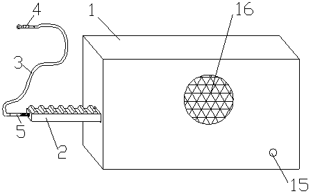
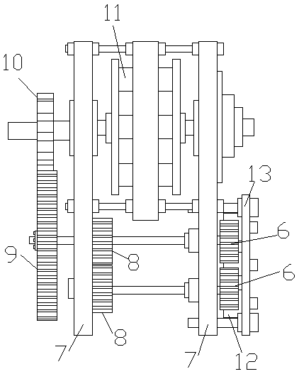
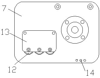
[0017] Such as figure 1 , figure 2 , image 3 with Figure 4 As shown, a new energy vehicle energy recovery power generation system is composed of a casing 1, a drive rack 2, a transmission line 3, and an energy conversion power generation mechanism. A heat dissipation window 16 is provided on the side of the casing, and the energy conversion power generation mechanism is built in the casing In 1, the energy conversion power generation mechanism includes two front and rear unidirectional bearings 6, a large gear plate 9, a pinion disk 10, and a generator 11. The front and rear unidirectional bearings 6 are respectively fixed on the bracket, and the rear unidirectional bearing passes through one The transmission gear plate 8 is connected with the large gear plate 9. The transmission gear plate at the end of the one-way bearing at the front meshes and connects with the transmission gear plate at the end of the one-way bearing at the back. A number of load-bearing wheels 12 are in...


PUM


Abstract

The invention provides a new energy motor vehicle energy recovery power generating system. The system is composed of a machine shell, a drive rack, a transmission line and an energy conversion power generating mechanism. The energy conversion power generating mechanism comprises two front and back one-way bearings, a big gear wheel, a small gear wheel and a power generator. One end of the transmission line is connected to the lower end of a damping spring of a chassis, the outer wall of the transmission line is fixed to the portion, at the upper end of the damping spring, of the vehicle chassis, the other end of the transmission line is connected with the drive rack, and the drive rack drives the one-way bearings to rotate. By means of gear transmission, the change of the distance gap between the lower portion of a tire vibration damper and the chassis in the driving process of the vehicle chassis is converted into dynamic energy to drive the power generator to work to generate power,the drive rack cooperates with the two front and back one-way bearings to convert stretching and shrinking of the gap between the vehicle chassis and the tire damper into continuous dynamic energy transmission, in one direction, of a power generator system, the power generator rotates without interruption, and meanwhile, as jolts from the ground are stably absorbed by the power generating system,a damping system can operate more smoothly.

Description

Technical field [0001] The invention relates to the technical field of motor vehicle vibration power generation, in particular to a new energy motor vehicle energy recovery power generation system. Background technique [0002] At present, most of the energy we use is fossil energy accumulated by solar energy for a long time. It is a non-renewable energy. The distribution of fossil energy on the earth is uneven and the reserves are limited. In the process of using fossil energy, it will generate greenhouse gases that cause environmental pollution. Affected the quality of human life and health. [0003] At present, new energy electric vehicles are the development goals pursued by global auto companies. Environmentally friendly and clean electric vehicles are also development projects advocated by governments. The world is not affected by technology except that the mileage of Tesla vehicles can be comparable to that of gasoline vehicles. The mileage of an electric car can satisfy co...

Claims


Application Information

Patent Timeline
Patent Type & Authority Applications(China)
IPC IPC(8): F03G7/08B60K25/10
CPCF03G7/08B60K25/10B60K2025/103
Inventor 李文浩李子信李秋红
Owner 李子信
Why Eureka
Try Eureka