
Acoustic emission source positioning method and system based on linear weighted least square method

A least square method and acoustic emission source technology, which is applied in radio wave measurement systems, material analysis and positioning using acoustic wave emission technology, can solve problems such as real-time changes, heavy weights, and greater impact on positioning results

Active Publication Date: 2020-07-10
CENT SOUTH UNIV
View PDF15 Cites 4 Cited by
  • Summary
  • Abstract
  • Description
  • Claims
  • Application Information

AI Technical Summary

Problems solved by technology

However, the traditional AE source localization method has the following problems: (1) Most of the traditional methods need to pre-determine the wave velocity, but in the real engineering environment, the wave velocity is difficult to measure accurately, or even changes in real time or is unknown
Therefore, the pre-measurement of wave velocity limits the application of traditional methods, and the error of wave velocity measurement will affect the accuracy of AE source location
(2) Due to the square root operation of the distance-time equation between the sensor and the acoustic emission source, the traditional method often has no solution and multiple solutions
(3) The traditional method ignores the estimation of the residual error of the equation, which makes the positioning results biased
(4) Some methods need to select a sensor as a reference sensor. During the positioning process, the data of the reference sensor is used more times than other sensors. In fact, the data of the reference sensor occupies a greater weight in the positioning calculation, which affects the positioning results. Larger, if the data of the reference sensor has large noise, it will directly affect the positioning accuracy of the acoustic emission source
(5) In the traditional method, the intermediate variable and the wave velocity are coupled with each other, resulting in the difficulty of matrix inversion

Method used


Image

  • Acoustic emission source positioning method and system based on linear weighted least square method
  • Acoustic emission source positioning method and system based on linear weighted least square method
  • Acoustic emission source positioning method and system based on linear weighted least square method

Examples


Embodiment 1

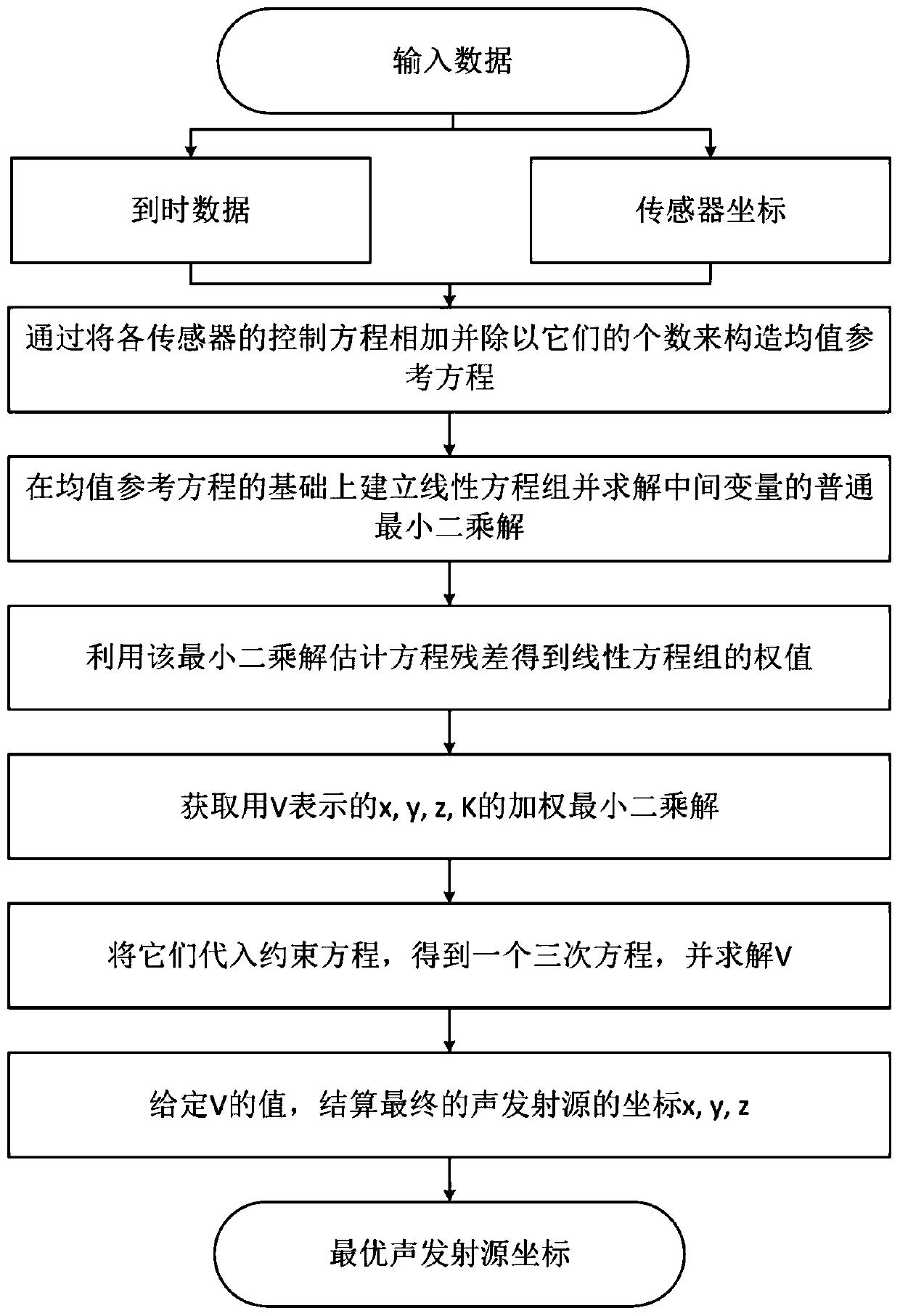
[0103] This embodiment provides a method for locating an acoustic emission source based on a linearly weighted least squares method, including the following steps:

[0104] Step 1, adding the distance time equations between each sensor and the acoustic emission source and dividing by the number of sensors to obtain the mean value reference equation (average reference equation);

[0105] Step 2. Based on the mean value reference equation, the nonlinear control equations composed of the distance time equations between each sensor and the acoustic emission source are converted into linear equations;

[0106] Step 3. Substitute the coordinates of each sensor and the time data when they receive the acoustic emission signal into the linear equations, and calculate the ordinary least squares solution V of the intermediate variables V and K (1) and K (1) , and then use them as prior solutions to estimate the covariance matrix Ψ of the linear equation; where the intermediate variable ...

Embodiment 2

[0111]In this embodiment, on the basis of embodiment 1, in said step 1, the expression of the mean value reference equation is as follows:

[0112]

[0113] Among them, x, y and z respectively represent the three components of the coordinate θ of the acoustic emission source; x j ,y j and z j Represent the three components of sensor j coordinates; t j Indicates the time when sensor j receives the acoustic emission signal, and M indicates the number of sensors.

Embodiment 3

[0115] Present embodiment is on the basis of embodiment 2, and in described step 2, linear equations expression is as follows:

[0116] L i =a i x+b i y+c i z+d i K+e i V

[0117] Among them, L i 、a i , b i 、c i 、d i and e i are intermediate variables, and their expressions are:

[0118]

[0119]

[0120]

[0121]

[0122]

[0123]

[0124] And i=1, 2, . . . , M.


PUM


Abstract

The invention discloses an acoustic emission source positioning method and system based on a linear weighted least square method. The method comprises the following steps: 1) obtaining a mean value reference equation according to a distance time equation between each sensor and an acoustic emission source; 2) obtaining a linear equation set based on the average reference equation; 3) based on thelinear equation set, calculating common least square solutions V (1) and K (1) of intermediate variables V and K so as to estimate a covariance matrix psi of the linear equation; 4) acquiring a weightmatrix W according to the psi, and calculating weighted least square solutions theta (2) and K (2) of acoustic emission source coordinates theta and K expressed by V; 5) substituting theta (2) and K(2) into the mean value reference equation to obtain a unary cubic equation about the V; and 6) solving the unary cubic equation, taking a root closest to V (1) as a V closed-form solution V (2), andsubstituting into theta (2) to obtain a final acoustic emission source coordinate. In the invention, positioning precision is high.

Description

technical field [0001] The invention relates to an acoustic emission source location method and system based on a linear weighted least square method. Background technique [0002] Acoustic emission positioning technology is an important non-destructive testing method, which is widely used in underground tunnels, deep mining, petrochemical, aerospace and other industries. Accurate identification of microscopic fracture and damage locations is the scientific basis for studying material failure mechanisms, predicting rockbursts, and safely operating large industrial equipment. Therefore, it is very valuable to develop a high-precision AE source localization method. However, the traditional AE source localization methods have the following problems: (1) Most of the traditional methods need to pre-determine the wave velocity, but in the real engineering environment, the wave velocity is difficult to measure accurately, or even changes in real time or is unknown. Therefore, the...

Claims


Application Information

Patent Timeline
Patent Type & Authority Applications(China)
IPC IPC(8): G01N29/14G01S5/22
CPCG01N29/14G01N2291/023G01S5/22
Inventor 芮艺超周子龙蔡鑫程瑞山陆建友
Owner CENT SOUTH UNIV
Learn More