Adaptive laser radar point cloud correction and positioning method based on sweeping robot

A technology of sweeping robot and laser radar, which is applied in the directions of instruments, surveying and navigation, electromagnetic wave re-radiation, etc., can solve the problems of inaccurate calibration results, ignoring the overall motion of the robot, and inability to accurately calibrate, so as to speed up the convergence speed Effect

Active Publication Date: 2020-07-10
SOUTH CHINA UNIV OF TECH
View PDF18 Cites 6 Cited by
  • Summary
  • Abstract
  • Description
  • Claims
  • Application Information

AI Technical Summary

Problems solved by technology

[0003] The traditional sweeping robot only uses the lidar sensor for positioning. Since the robot will move or rotate during the scanning process of the lidar, the obtained laser point cloud and the generated map will have a certain degree of distortion, and the degree of distortion is the same as that of the robot. The speed of motion is directly proportional, especially the rotational motion has a great influence on the distortion of the laser point cloud, so the laser point cloud needs to be corrected; some odometer interpolation methods are used to correct the data, but only a few odometer data are used and ignored The overall motion of the robot (LOAM: LidarOdometry and Mapping in Real-time) is not considered, and the existence of odometer measurement noise is not considered, so it cannot be corrected accurately
In engineering, rectilinear motion model correction is often used, but the correction effect on fast-moving robots is limited, and the robustness is not high
The polynomial fitting method is used to estimate the robot motion, but for a robot moving in a straight line, it often leads to overfitting, thus losing the overall information of the motion, and the correction results are inaccurate (Improved Techniques for Grid Mapping with Rao-BlackwellizedParticle Filters)

Method used


Image

  • Adaptive laser radar point cloud correction and positioning method based on sweeping robot
  • Adaptive laser radar point cloud correction and positioning method based on sweeping robot
  • Adaptive laser radar point cloud correction and positioning method based on sweeping robot

Examples


Embodiment Construction

[0048] The accompanying drawings are for illustrative purposes only, and should not be construed as limiting the present invention; in order to better illustrate this embodiment, certain components in the accompanying drawings will be omitted, enlarged or reduced, and do not represent the size of the actual product; for those skilled in the art It is understandable that some well-known structures and descriptions thereof may be omitted in the drawings. The technical solutions of the present invention will be further described below in conjunction with the accompanying drawings and embodiments.

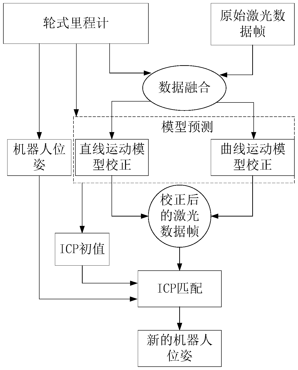
[0049] Such as figure 1 As shown, the adaptive lidar point cloud correction and positioning method based on the sweeping robot includes the following steps:

[0050] S1. When the sweeping robot is moving, it collects a new frame of data through the laser radar mounted on the robot. Assume that after the previous frame of data is released, the time stamp is t s , the pose of the sweepin...


PUM


Abstract

The invention provides an adaptive laser radar point cloud correction and positioning method based on a sweeping robot. The adaptive laser radar point cloud correction and positioning method comprisesthe following steps: S1, collecting a frame of new data through a laser radar carried on the robot; s2, acquiring a distance d and a rotation angle theta through a wheel type odometer, and speculating and estimating a pose corresponding to each odometer timestamp of the robot until one period of laser data frame acquisition is finished; s3, considering existence of errors, fitting the pose of therobot, and calculating a mean square error after a fitting result; s4, calculating the coordinate P'k-1 of each laser point cloud relative to the pose Tk-1 of the sweeping robot; s5, obtaining laserpoint cloud coordinates on the pose Tk of the sweeping robot, carrying out ICP matching on two adjacent frames of data, and obtaining the pose Tk of the sweeping robot. According to the method, the fitting model is adaptively selected according to the mean square error result, and the problems of map distortion and inaccurate positioning caused by laser point cloud distortion due to movement of the sweeping robot are solved.

Description

technical field [0001] The invention relates to the field of robot positioning, and more specifically, to an adaptive lidar point cloud correction and positioning method based on a sweeping robot. Background technique [0002] With the development and progress of science and technology, the cost of lidar, which is often used in the military field, has been greatly reduced, which makes it possible for commercial applications. Lidar has good monochromaticity, high brightness, strong directionality, and anti-interference Strong, strong resolution, small and light equipment, etc., especially in speed measurement and robot positioning, it has a wide range of applications. The wheel odometer can quickly measure the moving distance and rotation angle, has high positioning accuracy in a short time and without slipping, and the encoder is cheap and suitable for commercial applications. As the first batch of commercial service robots, sweeping robots have entered thousands of househo...

Claims


Application Information

Patent Timeline
IPC IPC(8): G01S17/86G01S17/06G01S17/93G01S7/497G01C23/00
CPCG01S17/06G01S17/93G01S7/497G01C23/00
Inventor 罗永恒魏武黄林青李奎霖周方华
Owner SOUTH CHINA UNIV OF TECH
Why Eureka
Try Eureka