Supercharge Your Innovation With Domain-Expert AI Agents!

Improved machining drilling machine

An improved technology for processing drills, which is applied in metal processing equipment, parts of boring machines/drilling machines, metal processing machinery parts, etc., can solve problems such as waste of cost, low processing accuracy, and low production efficiency, so as to avoid difficult collection and improve Productivity and workload enhancement effects

Inactive Publication Date: 2020-07-14
南昌金久科技有限公司
View PDF16 Cites 2 Cited by
  • Summary
  • Abstract
  • Description
  • Claims
  • Application Information

AI Technical Summary

Problems solved by technology

[0002] Drilling machine refers to a machine tool that mainly uses a drill bit to process holes on the workpiece. The drilling machine has a simple structure and relatively low machining accuracy. It can drill through holes and blind holes, replace special tools, expand, countersink, ream or tap. When the drilling machine is equipped with process equipment, it can also be used for boring. The drilling machine is equipped with a universal workbench and can also perform drilling, reaming, reaming and other processing. The drilling machine is an indispensable equipment for machinery manufacturing and various repair factories. One, existing drilling machine still has certain deficiency in use
[0003] The following problems often exist in the existing drilling machine during operation: a: when the existing drilling machine is drilling parts, it often produces some smaller metal shavings and wires, which are not easy to collect. directly sweep the metal shavings and metal wires to the ground and discard them, thereby causing waste and waste of cost; b: the existing drilling machine often uses a drill bit to process multiple parts when processing, which is extremely time-consuming and low in production efficiency during processing , greatly enhanced the workload of employees during production

Method used


Image

  • Improved machining drilling machine
  • Improved machining drilling machine
  • Improved machining drilling machine

Examples


Embodiment Construction

[0025] In order to make the technical means realized by the present invention, creative features, goals and effects easy to understand, the following combination Figure 1 to Figure 7 , to further elaborate the present invention.

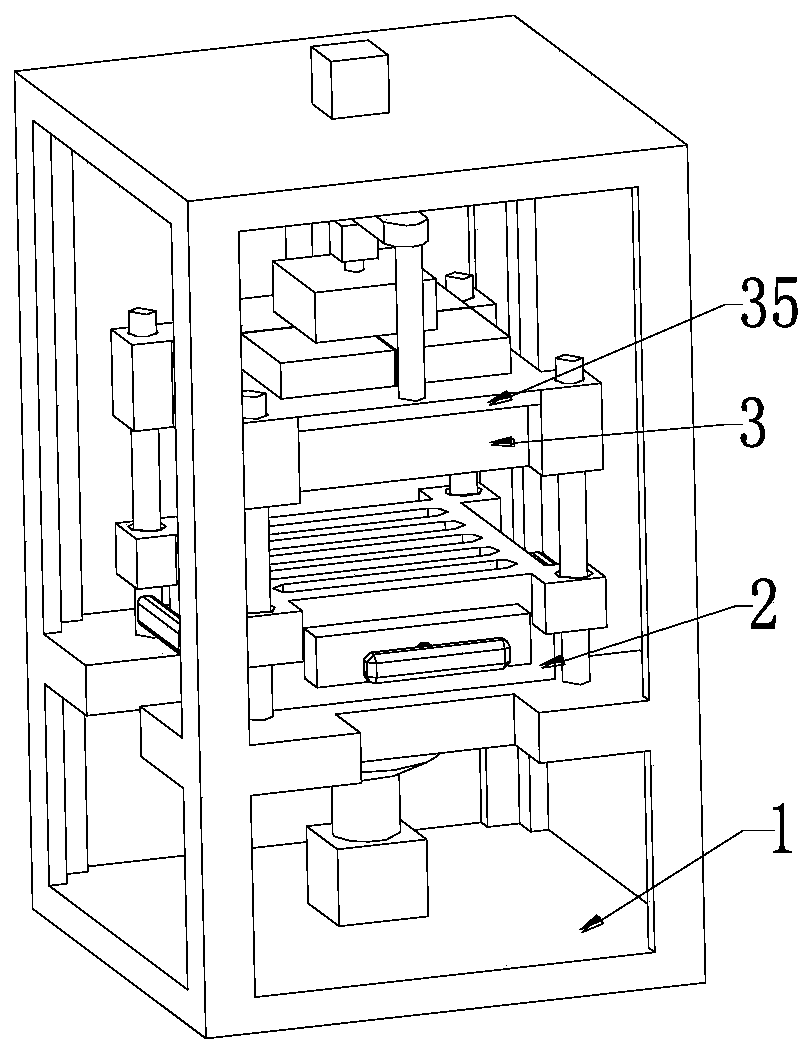
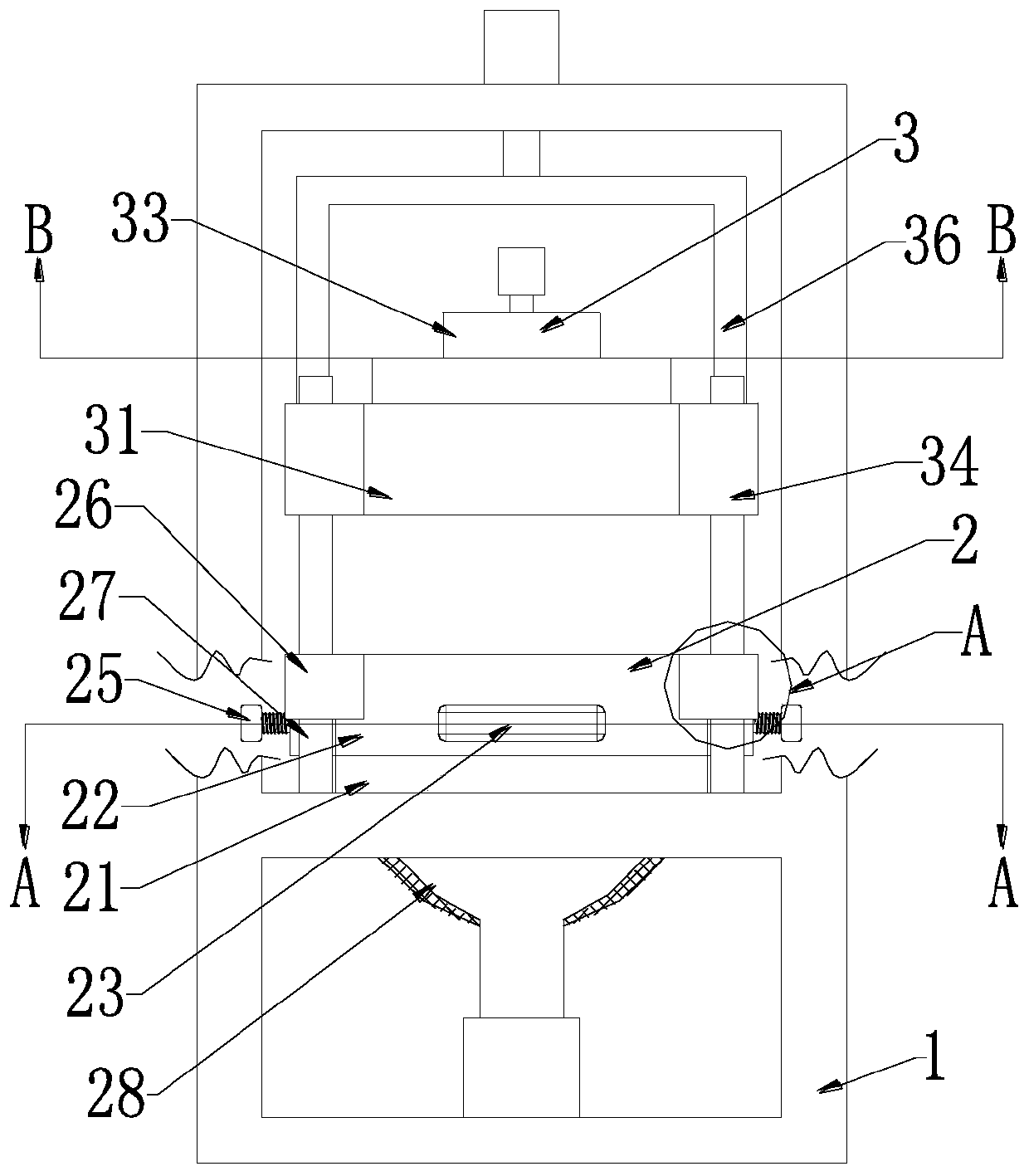
[0026] An improved processing drilling machine, including a mounting frame 1, a lower die set 2 and an upper die set 3, the lower die set 2 and the upper die set 3 are sequentially arranged inside the mounting frame 1 from bottom to top, wherein:

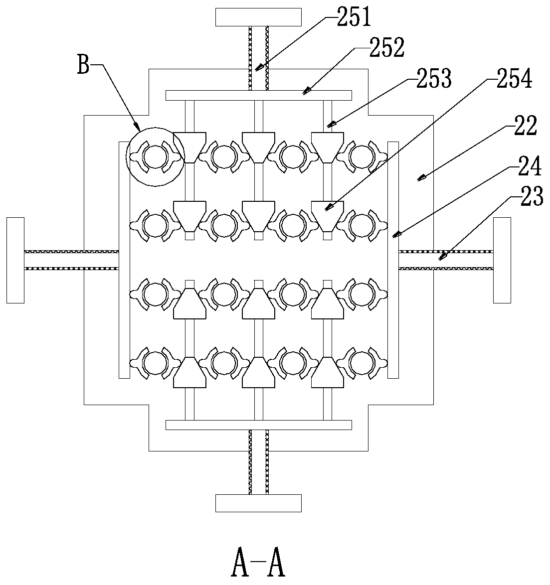
[0027] The lower mold set 2 includes a material passing board 21, a feeding board 22, a hand turntable 23, a clamping side plate 24, an inner clamping mechanism 25, a height limiting block 26, a guide column 27, a collection tank 28, a filter bag 29 and Aspirator, the feeding plate 21 is installed on the installation frame 1 by welding, the feeding plate 21 is uniformly provided with a feeding hole A, the aperture of the feeding hole A gradually increases from top to bottom, the feeding board 21 A mounti...


PUM


Abstract

The invention relates to an improved machining drilling machine. The improved machining drilling machine comprises a mounting frame, a lower die sleeve part and an upper die sleeve part, and the lowerdie sleeve part and the upper die sleeve part are sequentially arranged in the mounting frame from bottom to top. The drilling machine can solve following problems in operation process of existing drilling machine that a, when existing drilling machine is used for drilling part, some metal chips and metal wires which are small in size are often generated and are not easy to collect, and then themetal chips and the metal wires are directly swept to the ground to be discarded when the drilling machine is cleaned, so that waste of cost is caused; and b, when an existing drilling machine is usedfor machining, one drill bit is frequently used for machining a plurality of parts, time is extremely wasted in the machining process, the production efficiency is low, and the workload of workers isgreatly increased in the production process.

Description

technical field [0001] The invention relates to the technical field of drilling machine processing, in particular to an improved processing drilling machine. Background technique [0002] Drilling machine refers to a machine tool that mainly uses a drill bit to process holes on the workpiece. The drilling machine has a simple structure and relatively low machining accuracy. It can drill through holes and blind holes, replace special tools, expand, countersink, ream or tap. When the drilling machine is equipped with technological equipment, it can also be used for boring. The drilling machine can also be equipped with a universal workbench for drilling, reaming, reaming and other processing. The drilling machine is an indispensable equipment for machinery manufacturing and various repair factories. One, existing drilling machine still has certain deficiency in use. [0003] The following problems often exist in the existing drilling machine during operation: a: when the exis...

Claims


Application Information

Patent Timeline
Patent Type & Authority Applications(China)
IPC IPC(8): B23B47/00B23B47/30B23B39/16B23Q11/00
CPCB23B39/16B23B47/00B23B47/30B23Q11/0067
Inventor 黄丹丹江恰
Owner 南昌金久科技有限公司
Features
  • R&D
  • Intellectual Property
  • Life Sciences
  • Materials
  • Tech Scout
  • Unparalleled Data Quality
  • Higher Quality Content
  • 60% Fewer Hallucinations
Learn More