A traction device for a low-pressure turbine of an engine

A low-pressure turbine and low-pressure turbine shaft technology, used in metal processing, manufacturing tools, metal processing equipment, etc., can solve problems such as loss of bearings, reduce size and gravity, eliminate uneven circumferential clearance, and reduce installation risks.

Active Publication Date: 2022-04-26
AECC AVIATION POWER CO LTD
View PDF0 Cites 0 Cited by
  • Summary
  • Abstract
  • Description
  • Claims
  • Application Information

AI Technical Summary

Problems solved by technology

[0003] Aiming at the problem that the bearings are easily damaged during the installation process of the low-pressure turbine and the core engine of the existing engine, the invention provides a traction tool for the low-pressure turbine of the engine, which realizes the rapid assembly of the low-pressure turbine and the core engine, and solves the loss during the assembly process. bearing problem

Method used


Image

  • A traction device for a low-pressure turbine of an engine
  • A traction device for a low-pressure turbine of an engine
  • A traction device for a low-pressure turbine of an engine

Examples


Embodiment Construction

[0037] The present invention will be further described in detail below in conjunction with the accompanying drawings, which are explanations rather than limitations of the present invention.

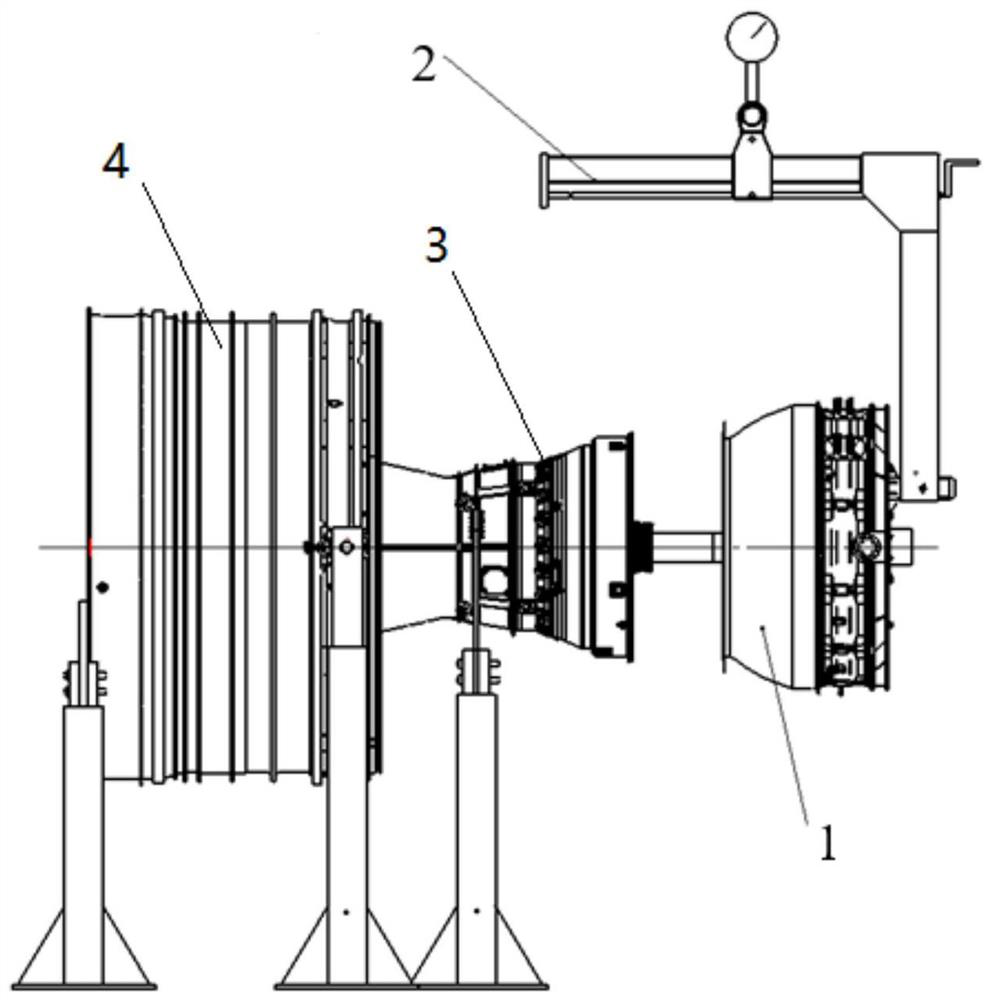
[0038] refer to Figure 1-11 , an assembly tool for a low-pressure turbine of an engine, including a positioning guide tool 5, a traction tool 6 and a torque multiplier 9.

[0039] The positioning guide tool 5 is coaxially connected with the low-pressure turbine shaft of the low-pressure turbine 1, the traction tool 6 is installed on the fan rotor 4, and the positioning guide tool 5 passes through the core machine 3 and the axis of the fan rotor 4 and is connected to the torque multiplier 9.

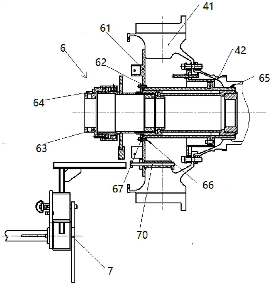
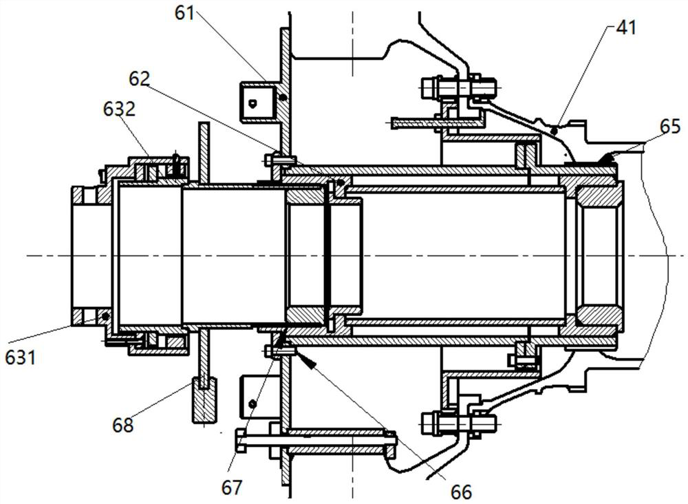
[0040] The positioning guide tool 5 includes a positioning shaft 51 , a traction shaft 52 , an adjustment shaft 57 and an adjustment rod 58 .

[0041] The traction shaft 52 and the positioning shaft 51 are both hollow shafts, one end of the positioning shaft 51 is embedded in one end of the tracti...


PUM


Abstract

The invention provides a traction tool for a low-pressure turbine of an engine, which includes a torque transmission bush and a traction bushing. To the outside of the fan rotor, during the assembly process of the low-pressure turbine, torque is applied externally to the traction shaft, and the traction shaft and the connecting sleeve rotate synchronously. During the rotation of the fan rotor, the traction shaft is driven to move axially through threads, thereby making the low-pressure The turbine shaft has dual forces of rotation and axial movement, so that the bearing cylindrical rollers on the low-pressure turbine shaft are gradually fitted into the outer ring of the bearing during rotation, which solves the mechanical problem of cylindrical rollers and bearing outer rings in the existing assembly process. Collision problem.

Description

technical field [0001] The invention relates to the technical field of engine assembly, in particular to a traction tool for a low-pressure turbine of an engine. Background technique [0002] The low-pressure turbine of the engine is a unit structure. The bearing inner ring, cage and bearing cylindrical roller of the four-point bearing of the engine are assembled on the low-pressure turbine shaft, which is a part of the low-pressure turbine unit; the bearing outer ring is assembled behind the high-pressure turbine rotor. On the journal, it is part of the core unit. During assembly, the pressure turbine and the core machine are assembled horizontally, the low-pressure turbine is horizontally assembled to the core machine unit under the action of traction, the bearing cylindrical roller enters the bearing outer ring horizontally, and the distance between the bearing cylindrical roller outer diameter and the bearing inner ring The gap is only 0.07mm, and the length of the low-...

Claims


Application Information

Patent Timeline
Patent Type & Authority Patents(China)
IPC IPC(8): B23P19/00
CPCB23P19/00
Inventor 宋树林马涛黄健崔宝锋焦晓冉任远哲冯雨堃白雪
Owner AECC AVIATION POWER CO LTD
Why Eureka
Try Eureka