
A cutter roll for glass fiber chopping machine

A cutting machine and glass fiber technology, applied in metal processing and other directions, can solve the problems of aggravating blade wear, unfavorable yarn arrangement, affecting production efficiency, etc., and achieve the effect of reducing blade temperature, improving production efficiency and prolonging service life.

Active Publication Date: 2021-07-20
重庆富强华威环保工程有限公司
View PDF6 Cites 0 Cited by
  • Summary
  • Abstract
  • Description
  • Claims
  • Application Information

AI Technical Summary

Problems solved by technology

However, because the surface of the glass fiber is coated with a sizing agent, it is highly viscous when wet and slippery, sticking to the surface of the blade or filling the gap between the knife grooves, resulting in unfavorable yarn arrangement
In the actual operation process, because the blade is stuck in the knife groove, the yarn discharge is unfavorable, and the wear of the blade is aggravated. After working for several hours, it is necessary to stop the machine to replace the blade and clean the knife roller, which seriously affects the production efficiency.

Method used


Image

  • A cutter roll for glass fiber chopping machine
  • A cutter roll for glass fiber chopping machine

Examples


Embodiment Construction

[0018] In order to make the purpose, technical solutions and advantages of the embodiments of the present invention clearer, the technical solutions in the embodiments of the present invention will be clearly and completely described below in conjunction with the drawings in the embodiments of the present invention. Obviously, the described embodiments It is a part of embodiments of the present invention, but not all embodiments. The components of the embodiments of the invention generally described and illustrated in the figures herein may be arranged and designed in a variety of different configurations.

[0019] Accordingly, the following detailed description of the embodiments of the invention provided in the accompanying drawings is not intended to limit the scope of the claimed invention, but merely represents selected embodiments of the invention. Based on the embodiments of the present invention, all other embodiments obtained by persons of ordinary skill in the art wi...


PUM


Abstract

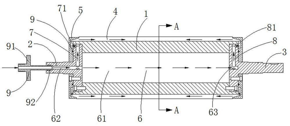
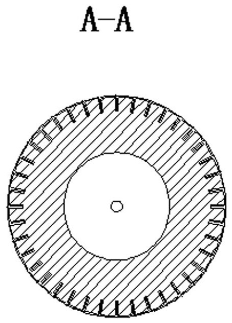
The invention discloses a cutter roll for a glass fiber chopping machine, which comprises a roll body, a plurality of blades arranged on the outer wall of the roll body, and pressure plates arranged at both ends of the roll body for fixing the blades; the roll The body is provided with a purge channel that communicates with the outside world to facilitate the cleaning of the cutting between the blades; the purge channel includes a plurality of first radial flow channels arranged at one end of the roller body, and a plurality of first radial channels arranged at the other end of the roller body. Two radial flow channels and an axial flow channel for connecting the first radial flow channel and the second radial flow channel with the outside. In the present invention, compressed air is introduced from the center of one end of the roller body, and the gas is introduced into the axial blade grooves at both ends of the blade through the purge channel, forming a purge from both ends of the axial blade groove to the middle, preventing cutting from entering the blade space In the gaps, it can effectively prevent the knife from sticking, and at the same time, it can also reduce the temperature of the blade, prolong the service life of the blade, and improve production efficiency.

Description

technical field [0001] The invention relates to the technical field of glass fiber processing equipment, in particular to a knife roller used for a glass fiber chopping machine. Background technique [0002] The chopping machine is currently the most commonly used fiber cutting tool; the chopping machine uses the relative rotation of the knife roller and the rubber roller to cut the fiber, which has the characteristics of low energy consumption and high production efficiency. However, because the surface of the glass fiber is coated with a sizing agent, it is highly viscous when wet and slippery, sticking to the surface of the blade or filling the gap between the knife grooves, resulting in unfavorable yarn arrangement. In the actual operation process, because the blade is stuck in the knife groove, the yarn discharge is unfavorable, and the wear of the blade is aggravated at the same time. After working for several hours, it is necessary to stop the machine to replace the b...

Claims


Application Information

Patent Timeline
Patent Type & Authority Patents(China)
IPC IPC(8): B26D7/18B26D1/36
CPCB26D1/36B26D7/1854
Inventor 肖高雄
Owner 重庆富强华威环保工程有限公司
Learn More