Sludge treatment device

A sludge treatment and sludge technology, applied in the field of sludge treatment devices, can solve the problems of increasing the output power of hydraulic equipment, decreasing the elastic strength, reducing the extrusion effect, etc., so as to improve the force balance, improve the extrusion power, Improve the effect of the closure effect

Active Publication Date: 2020-07-14
深圳华净环境科技有限公司
View PDF9 Cites 3 Cited by
  • Summary
  • Abstract
  • Description
  • Claims
  • Application Information

AI Technical Summary

Problems solved by technology

Although this structure can achieve the purpose of extruding sludge to filter water, due to the way of extruding on one side, the force on the entire fixed frame will be uneven. After long-term use, the entire frame will be deformed, and the hydraulic equipment and extrusion The distance between the platens reduces the squeeze effect
[0006] In addition, the spring is used as the buffer part between the extrusion plates. First, the spring itself has a limit compression width, which affects the extrusion width of the sludge in the interlayer; second, part of the extrusion force is offset by the spring force, which indirectly increases the pressure of the hydraulic equipment. The third is that the elastic strength of the spring decreases after long-term use, which affects the opening width of the extruded plate
[0007] There are also some equipment with a single treatment function, which can only deal with a certain type of sludge, and the adaptability is too low

Method used


Image

  • Sludge treatment device
  • Sludge treatment device
  • Sludge treatment device

Examples


Embodiment Construction

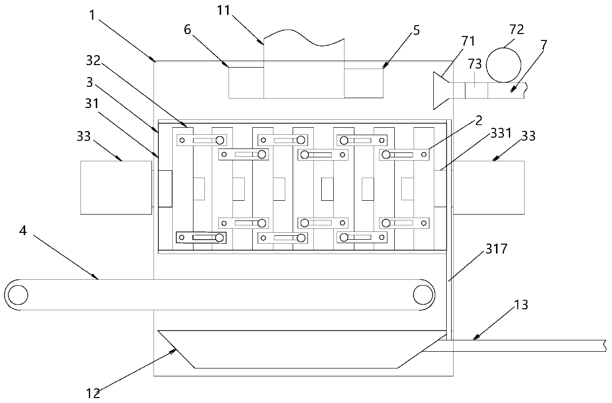
[0040] Such as figure 1 As shown, one embodiment of the present invention provides a sludge treatment device, including a hollow rectangular housing 1 as a workplace, and a sludge input pipeline 11 for external sludge input is arranged in the housing 1, and the imported sludge A filter press device 3 for press-filtering the mud, a conveyor belt 4 for outputting the sludge after the filter press, and a collection box 12 for receiving scattered sludge and fluid.

[0041] One end of the sludge input pipe 11 is used to connect the sludge supply point, and the other end extends into the housing 1, and the amount of sludge input can be controlled by the power equipment.

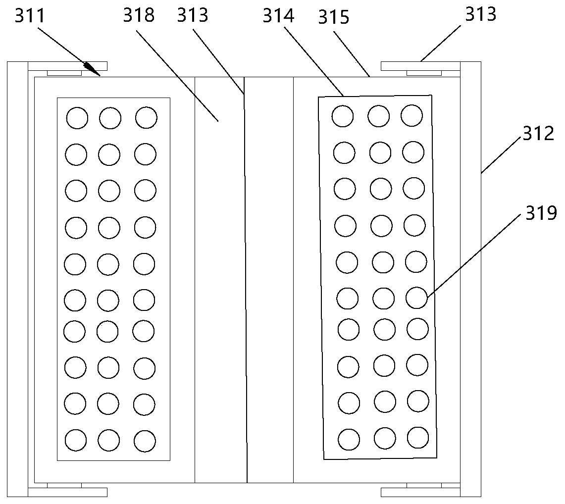
[0042]The filter press device 3 is located below the sludge input pipeline 11, and is used to receive the sludge input by the sludge input pipeline 11 and compress and filter it. It generally includes a squeeze chamber 31 for accommodating sludge, and is located in the squeeze chamber 31 to squeeze the sludge. The...


PUM


Abstract

The invention provides a sludge treatment device comprising a hollow shell, the shell is provided with: a sludge input pipeline, a filter pressing device, a hydraulic machine, a conveying belt and a collecting box, wherein the filter pressing device comprises an extrusion bin, two oppositely-opened movable doors are arranged at the upper portion and the bottom of the extrusion bin respectively, containing spaces for liquid to flow are formed in the middles of the movable doors, filter plates are arranged on the sides facing the interiors of the extrusion bins, and blow-off pipes for discharging internal liquid are arranged in the containing spaces; a plurality of extrusion plates are arranged in the extrusion bin side by side, the extrusion plates are movably connected through connecting plates, and hydraulic machines are arranged on the two sides, opposite to the extrusion bin, of the shell and extend into the shell and the extrusion bin through hydraulic rods to be connected with theadjacent extrusion plates. The conveying belt is located below the extrusion bin, and the collecting box is used for receiving sludge and liquid falling from the upper portion. By means of the hydraulic machines symmetrically installed on the two sides, extrusion power can be improved, thrust can be kept balanced, the overall structure cannot be affected, and the final sludge water content is only 40%-60%.

Description

technical field [0001] The invention relates to the field of environmental protection, in particular to a sludge treatment device capable of improving the filter press effect and having multiple treatment functions. Background technique [0002] The current sludge treatment method is a process of reducing, stabilizing and harmless sludge such as concentration, conditioning, dehydration, stabilization, drying or incineration. [0003] Sludge is generally a product of sewage treatment. The sludge produced in different industries has different components, but they all contain a large amount of organic matter, heavy metals, and mold. If they are directly discharged without subsequent treatment, they will cause serious pollution to the environment. , Therefore, it is often necessary to carry out various processing on the sludge to reduce the harm and at the same time reuse it. [0004] One of the steps in sludge treatment is to compress it for dehydration treatment, but the exis...

Claims


Application Information

Patent Timeline
Patent Type & Authority Applications(China)
IPC IPC(8): C02F11/122
CPCC02F11/122
Inventor 解志强
Owner 深圳华净环境科技有限公司
Why Eureka
Try Eureka