
Flexible OLED display device

A display device and flexible technology, applied in the manufacturing of electrical components, electric solid-state devices, semiconductor/solid-state devices, etc., can solve the problems of reduced impact resistance, display failure, OLED panel damage, etc. Insufficient impact force and improved reliability

Inactive Publication Date: 2020-07-14
WUHAN CHINA STAR OPTOELECTRONICS SEMICON DISPLAY TECH CO LTD
View PDF7 Cites 3 Cited by
  • Summary
  • Abstract
  • Description
  • Claims
  • Application Information

AI Technical Summary

Problems solved by technology

[0004] At present, to realize the dynamic bending of OLED displays, the surface of the display panel (Panel) can no longer be covered and protected by a rigid cover glass (Cover Glass), but can only be replaced by a non-rigid and bendable flexible cover window. (Flexible Cover Window, FCW) protects the Panel. Although the non-rigid flexible cover window has good performance in bending, it can improve the bending performance of the product, but its surface hardness, impact strength and user The hand feel is not as good as the traditional glass cover. Therefore, when the OLED display uses a flexible cover window instead of the glass cover, there is a problem that the Panel’s standard impact resistance is greatly reduced, and it does not perform well in impact tests such as falling balls / pen drops. The flexible cover window cannot effectively withstand the impact force and converts the vertical downward impact force into a horizontal force, resulting in damage to the OLED panel under the flexible cover window under the impact force, resulting in display failure

Method used


Image

  • Flexible OLED display device

Examples


Embodiment Construction

[0022] In order to further illustrate the technical means adopted by the present invention and its effects, the following describes in detail in conjunction with preferred embodiments of the present invention and accompanying drawings.

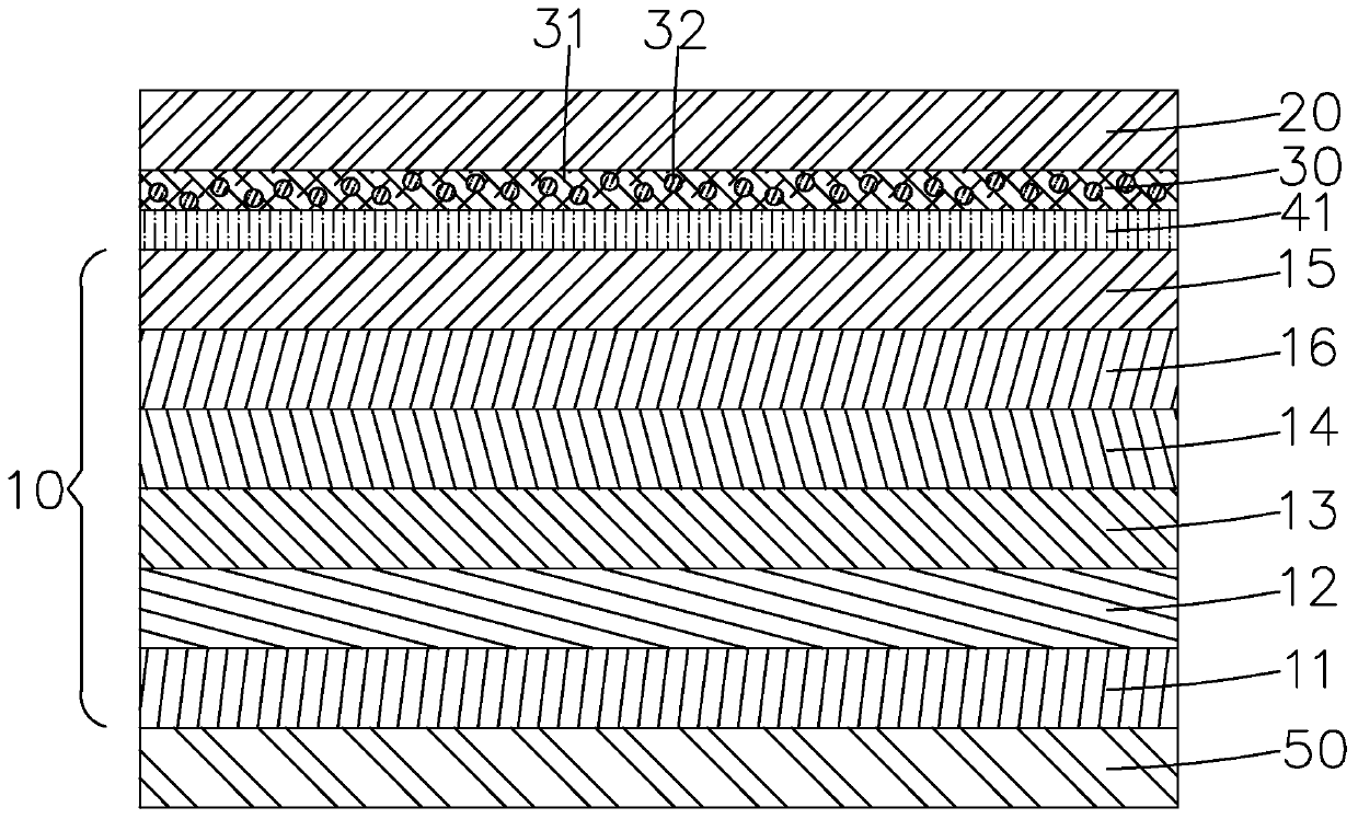
[0023] see figure 1 , the present invention provides a flexible OLED display device, comprising a middle frame 50, an OLED display panel 10 arranged on the middle frame 50, a flexible cover window 20 arranged on the OLED display panel 10, a flexible cover window 20 arranged on the OLED display panel The impact-resistant layer 30 between the flexible cover window 20 and the impact-resistant layer 30 and the adhesive layer 41 between the impact-resistant layer 30 and the OLED display panel 10 .

[0024] Specifically, the anti-shock layer 30 includes an expansive fluid material 31 and hard particles 32 doped in the expansive fluid material 31 . Since the expansive fluid material 31 has the characteristic that the apparent shear viscosity increas...


PUM

PropertyMeasurementUnit
particle diameteraaaaaaaaaa
thicknessaaaaaaaaaa

Abstract

The invention provides a flexible OLED display device. The flexible OLED display device comprises an OLED display panel, a flexible covering window arranged on the OLED display panel, and an anti-impact layer arranged between the OLED display panel and the flexible covering window, wherein the anti-impact layer comprises an expansible fluid material and hard particles doped in the expansible fluidmaterial. According to the invention, the characteristic that the apparent shear viscosity of the expansible fluid material is improved along with the increase of the shear rate is utilized, and theanti-impact layer is softer in texture in a static state or under the condition of smaller external force, so the flexible OLED display device can be normally bent; when a sudden external force impactoccurs, the expansible fluid material hardens instantaneously, and the hardness of the anti-impact layer is further improved by the hard particles, so the anti-impact layer can effectively block external impact force and protect the OLED display panel from being damaged by the external impact force, the problem of insufficient anti-impact force faced by the dynamically bent product is effectivelysolved, and the reliability of the product is improved.

Description

technical field [0001] The invention relates to the field of flat panel display technology, in particular to a flexible OLED display device. Background technique [0002] Organic Light-Emitting Diode (OLED) displays have the characteristics of self-illumination, high brightness, wide viewing angle, high contrast, flexibility, and low energy consumption. Has begun to gradually replace the traditional liquid crystal display. At present, the application of OLED display panels has become a high-end symbol from small-sized mobile phone display screens to large-sized high-resolution flat-panel TVs. [0003] With the development of display technology, mobile phone display technology has entered the era of flexible OLED displays, but the current application of OLED displays is still limited to the static bending stage, and no real flexible OLED displays have been realized, at least not mass production. Dynamic Foldable flexible OLED screen; as users have higher requirements for di...

Claims


Application Information

Patent Timeline
Patent Type & Authority Applications(China)
IPC IPC(8): H01L51/52
CPCH10K50/844
Inventor 黄鹏
Owner WUHAN CHINA STAR OPTOELECTRONICS SEMICON DISPLAY TECH CO LTD
Learn More