Handle

A handle and plug technology, applied in the handle field, can solve the problems of the transducer and handle becoming larger, the performance loss of the transducer, etc., so as to reduce the feeling of the handle shaking, reduce performance loss, and reduce noise.

Pending Publication Date: 2020-07-17
桂林市锐锋医疗器械有限公司
View PDF0 Cites 0 Cited by
  • Summary
  • Abstract
  • Description
  • Claims
  • Application Information

AI Technical Summary

Problems solved by technology

The handle needs to be provided with a matching polygonal anti-rotation step on the transducer and the plug respectively to prevent the relative rotation of the transducer and the plug. The anti-rotation step makes a hard contact between the transducer and the plug, forcing performance loss of the transducer

Method used


Image

  • Handle
  • Handle
  • Handle

Examples


Embodiment 1

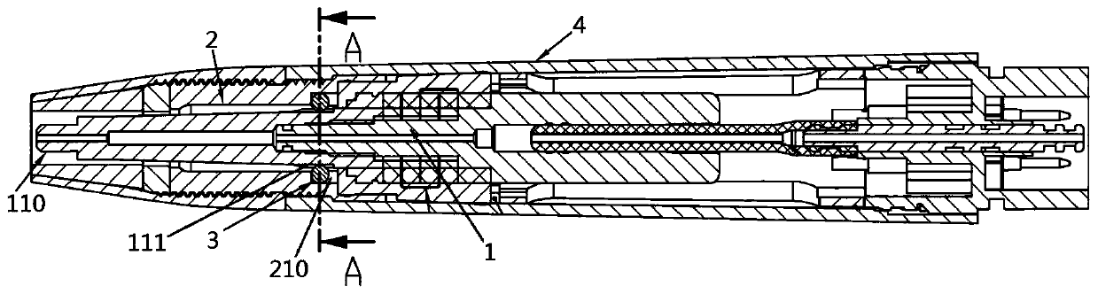
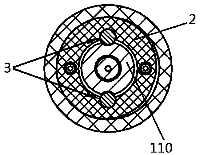
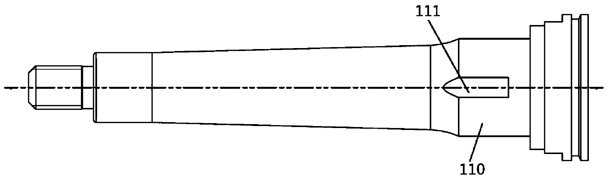
[0022] Such as Figure 1 to Figure 5 As shown, a handle at least includes a transducer 1, a plug 2 and a marble 3, the plug 2 is sleeved on the horn 110 of the transducer 1, and the horn 110 and the plug 2 There is at least one cavity, the cavity is composed of a groove a111 on the outer wall of the horn 110 and a groove b210 on the inner wall of the plug 2, a marble 3 is built in the cavity, and the bullet in the cavity The bead 3 is simultaneously in the groove a111 and the groove b210 constituting the cavity.

Embodiment 2

[0023] Example 2, such as Figure 1 to Figure 5 As shown, the present embodiment is a further optimization carried out on the basis of embodiment 1, which is specifically as follows:

[0024] The difference between the radius of the arc cut by the groove a111 in the radial direction and the radius of the marble 3 is greater than 0.05 mm, which facilitates the loading and unloading of the marble 3 .

Embodiment 3

[0025] Example 3, such as Figure 1 to Figure 5 As shown, the present embodiment is a further optimization carried out on the basis of embodiment 1 or 2, which is specifically as follows:

[0026] The arc center angle of the arc cut radially by the groove b210 is greater than 180 degrees, and the diameter of the marble 3 is greater than the chord length of the arc cut radially by the groove b210, which can ensure that the marble 3 will not slip from the plug after the installation is completed. 2, and the groove a111 can be an arc-shaped groove, U-shaped groove, V-shaped groove or square groove, etc. If it is an arc-shaped groove, the arc center angle can be any angle, as long as the horn can be realized 110 and the pinball 3 are mutually limited. In practice, the groove b210 and the groove a111 are both arc-shaped grooves, and the angles of their arc centers are preferably 223° and 94° respectively.


PUM


Abstract

The invention relates to a handle. The handle at least comprises a transducer, a plug and a ball, wherein the plug sleeves the amplitude transformer of the transducer, at least one cavity is arrangedbetween the amplitude transformer and the plug, and the cavity consists of a groove a positioned on the outer wall surface of the amplitude transformer and a groove b positioned on the inner wall surface of the plug; and the ball is arranged in the cavity, and the ball in the cavity is simultaneously positioned in the groove a and the groove b which form the cavity. The handle has the beneficial effects that: polygonal anti-rotation steps do not need to be arranged on the amplitude transformer and the plug, and the transducer and the handle can be made smaller under the condition that the performance is not reduced; when the handle works, a ball is not in hard contact with the amplitude transformer, a suspended state is kept, and the vibration force of the transducer cannot be directly transmitted to the plug, namely, the vibration force of the transducer cannot be transmitted to the shell, so that unnecessary performance loss of the transducer can be reduced; and meanwhile, the hand vibration feeling of the handle when an operator uses the handle is reduced, and the noise when the handle works can be reduced.

Description

technical field [0001] The invention relates to ultrasonic medical equipment, in particular to a handle. Background technique [0002] Dental ultrasonic medical equipment refers to the electrical medical equipment that realizes the expected function and function through the ultrasonic vibration generated by the ultrasonic transducer, including ultrasonic tooth scaler, ultrasonic bone knife machine, etc. Ultrasonic tooth scaler mainly generates high-frequency oscillation signal by high-frequency oscillation circuit and acts on the ultrasonic transducer, using inverse piezoelectric effect to generate ultrasonic vibration, the working tip is excited to generate resonance, the working tip and plaque, stones, The direct contact of dental plaque and tea plaque produces the effect of scraping or shearing, and removes the pollution layer attached to the root canal wall, so as to achieve the effect of cleaning and rinsing the root canal. Ultrasonic osteotome machine uses high-intens...

Claims


Application Information

Patent Timeline
Patent Type & Authority Applications(China)
IPC IPC(8): A61B17/16A61B17/32A61C17/20B06B1/06F16B1/02
CPCA61B17/16A61B17/320068A61C17/20B06B1/06B06B2201/55B06B2201/76F16B1/02
Inventor 穆连彬廖秋平谢其煜蓝振华
Owner 桂林市锐锋医疗器械有限公司
Why Eureka
Try Eureka