Water conservancy gate

A gate and water conservancy technology, applied in the field of water conservancy, can solve the problems of normal use of water conservancy gates, gaps in water channels, adhesion of silt and stones, etc.

Active Publication Date: 2020-07-17
宁夏亚兴达建筑工程有限公司
View PDF9 Cites 5 Cited by
  • Summary
  • Abstract
  • Description
  • Claims
  • Application Information

AI Technical Summary

Problems solved by technology

[0003] Because there is a lot of viscous silt in the sea, especially the canals connected with seawater, due to the ebb and flow of the seawater for a long time, and the water volume of the canals is insufficient compared with the water volume of the sea, so that the silt and stones brought by the seawater will Stacked

Method used


Image

  • Water conservancy gate
  • Water conservancy gate
  • Water conservancy gate

Examples


Embodiment 1

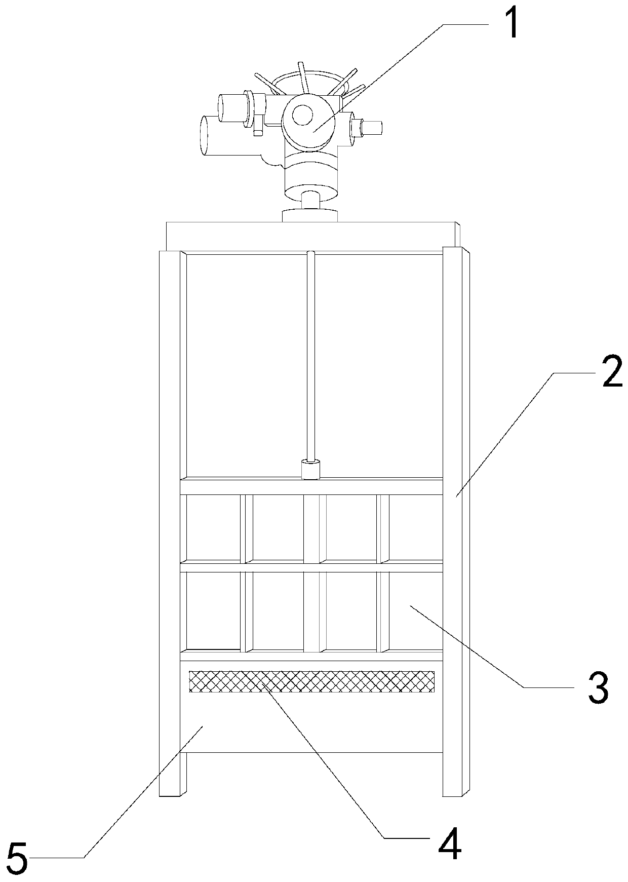
[0027] For example figure 1 -example Figure 5 Shown:

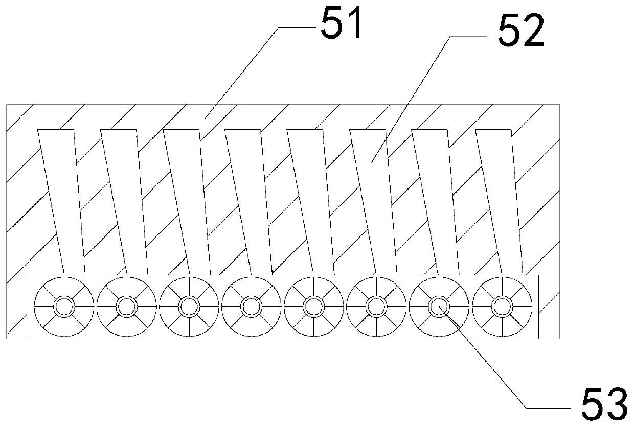
[0028] The invention provides a water conservancy gate, the structure of which includes a driver 1, an outer frame 2, a gate 3, a water permeable opening 4, and a mud cleaning mechanism 5. The driver 1 is connected to the gate 3 through the outer frame 2, and the gate 3 is connected to the outer The inner wall of the frame 2 is fitted with a gap, and the permeable port 4 and the mud-clearing mechanism 5 are an integrated structure, and the mud-clearing mechanism 5 is embedded and fixed at the bottom of the gate 3 .

[0029] Wherein, the mud cleaning mechanism 5 includes a housing 51, a water storage tank 52, and a cleaning roller 53. The water storage tank 52 is embedded in the inner position of the housing 51, and the cleaning roller 53 is movable with the inner wall of the housing 51 near the lower end. Together, the water storage tank 52 has an inverted trapezoidal structure, which can enhance the water pressure of t...

Embodiment 2

[0036] For example Figure 6 -example Figure 8 Shown:

[0037] Wherein, the opening and closing plate b3 includes a rolling column b31, a baffle b32, a sliding groove b33, and a bottom plate b34. The rolling column b31 is movably engaged with the sliding groove b33, and the baffle b32 is embedded and connected with the bottom plate b34. The sliding groove b33 and the baffle b32 are integrated structures, and the outer surface of the rolling column b31 is always in contact with the upper surface of the bottom plate b34, and can remove a small amount of silt adhered to the surface of the bottom plate b34 through the promotion of water flow.

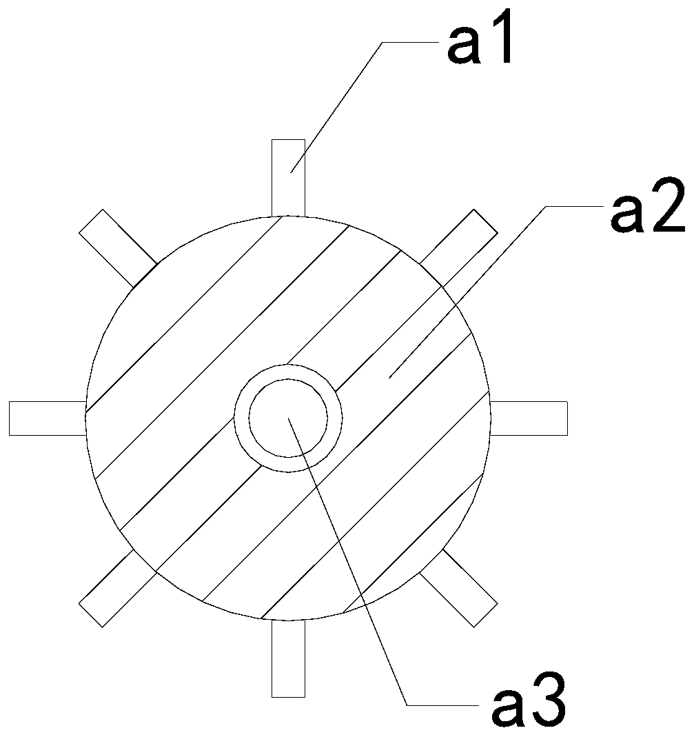
[0038]Wherein, the rolling column b31 includes a scraper c1, a cleaning block c2, a receiving column c3, an engaging roller c4, and a scraping mechanism c5. The scraper c1 is embedded in the outer surface of the receiving column c3, and the cleaning block c2 is installed Between the two adjacent scrapers c1, the engaging roller c4 is fix...


PUM


Abstract

The invention discloses a water conservancy gate. The water conservancy gate structurally comprises a driver, an outer frame, a gate body, a water permeable opening and a mud removing mechanism, wherein the driver is connected with the gate body through the outer frame; the gate body is in clearance fit with the inner wall of the outer frame; the water permeable opening and the mud removing mechanism are of an integrated structure; and the mud removing mechanism is embedded and fixed to the bottom of the gate body. When the gate body ascends to be opened, water flow in a water storage tank canimpact a linkage plate on a removing roller, accordingly, the water flow can continuously flush away sludge and stone attached to the removing roller, and the situation that the sludge and the stoneare likely to be attached to the bottom of the mud removing mechanism is avoided. Through thrust generated by the water flow to a rolling column on the opening and closing plate, the rolling column can slide downwards along a sliding groove, accordingly, a scraper on the rolling column can scrape away the sludge left on the upper surface of a bottom plate, and the situation that a small part of sludge high in viscosity is not likely to be thoroughly flushed away and continues to be attached to the bottom plate is avoided.

Description

technical field [0001] The invention relates to the field of water conservancy, in particular to a water conservancy gate. Background technique [0002] By closing the water conservancy sluice gate, it can play the functions of blocking flood and keeping tide, otherwise, opening the sluice gate can perform the functions of flood discharge and water intake, etc., and it is widely installed in large water areas such as river courses and coastal areas. Based on the above description, the inventor found that now Some water conservancy gates mainly have the following deficiencies, for example: [0003] Because there is a lot of viscous silt in the sea, especially the canals connected with seawater, due to the ebb and flow of the seawater for a long time, and the water volume of the canals is insufficient compared with the water volume of the sea, so that the silt and stones brought by the seawater will Stacked on the canal, so that when the sluice on the canal is opened, a mixtu...

Claims


Application Information

Patent Timeline
IPC IPC(8): E02B7/26E02B7/34
CPCE02B7/26E02B7/34
Inventor 曹志勇
Owner 宁夏亚兴达建筑工程有限公司
Why Eureka
Try Eureka