Steel structural beam type sliding stair and construction method

A technology for steel structure beams and stairs, applied in the direction of stairs, ladder-like structures, building structures, etc., can solve the problems that the safety and effectiveness of escape routes cannot be guaranteed, the calculation of overall force is not suitable, and the force of joint areas is complicated, etc., so as to facilitate engineering The effect of high quality, high promotional value, and reduced design workload

Active Publication Date: 2020-07-17
XIAN CHANGQING TECH ENG +1
View PDF5 Cites 0 Cited by
  • Summary
  • Abstract
  • Description
  • Claims
  • Application Information

AI Technical Summary

Problems solved by technology

[0003] 1. The force of the joint area is complex, and the joints connected by welding not only transmit the vertical shear force, but also transmit a large joint bending moment under the action of the earthquake force
The traditional welding connection will cause the connection part of the beam stair joint to bear a large bending moment before the main body of the structure is destroyed
[0004] 2. As required by the structural seismic design code, the stairwell should be effectively separated from the main structure, and should not be involved in the overall force calculation of the structure; if the structural design does not take corresponding structural measures to effectively separate the stairwell from the main structure, the stairwell will be compared Large stiffness should be involved in the calculation of the overall force of the structure, which will lead to further aggravation of the structural calculation
Due to the design flaws of the traditional steel structure beam staircase, under the action of an earthquake, the joints of the stairwell will bear a large bending moment and be damaged before the main body of the structure, which cannot guarantee the safety and effectiveness of the escape route.
[0006] 4. Welding connections are not conducive to efficient construction, resulting in the inability of some prefabricated steel components to be spliced ​​and installed quickly and reasonably on site

Method used


Image

  • Steel structural beam type sliding stair and construction method
  • Steel structural beam type sliding stair and construction method
  • Steel structural beam type sliding stair and construction method

Examples


Embodiment 1

[0046] according to Figure 1-9 The shown steel structure beam type sliding staircase at least includes a staircase foundation 1, a structural bottom frame ladder beam 6 and a platform beam, and the upper part of the structural bottom frame ladder beam 6 is detachably connected to the platform beam by bolts, and is characterized in that: It also includes a limit sliding device, a non-bottom frame beam 8, a structural frame beam 7 and a connecting mechanism; the limit slide device is connected to the beam type staircase foundation 1, and the lower part of the structural bottom frame ladder beam 6 passes through the limit The sliding device is connected with the stair foundation 1; two sides of the structural frame beam 7 are respectively provided with a pick ear 9, and the middle part of the non-bottom frame beam 8 is provided with a pick ear 9; There are through holes, and the connecting mechanism connects and fixes the non-bottom frame beam 8 and the structural frame beam 7 t...

Embodiment 2

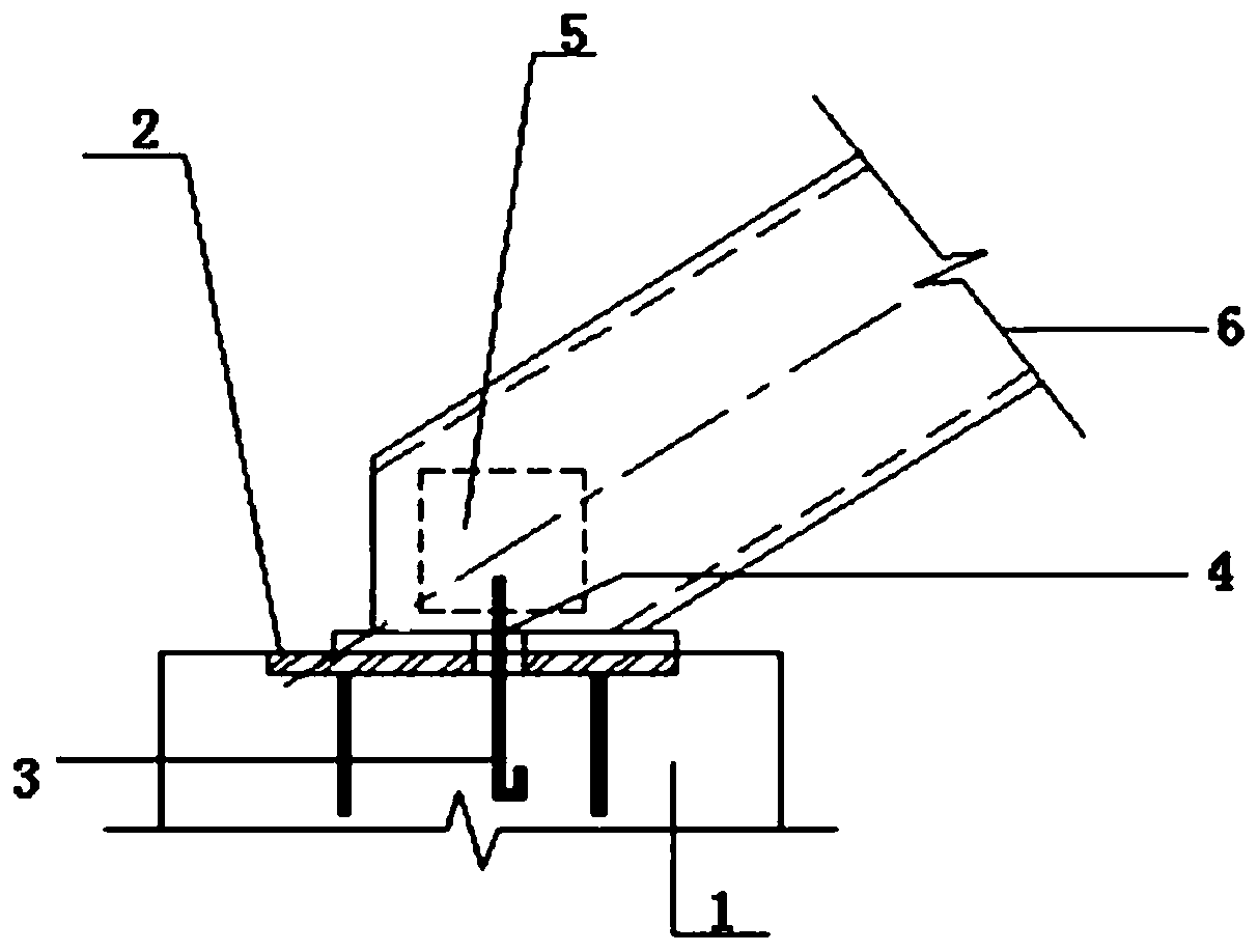
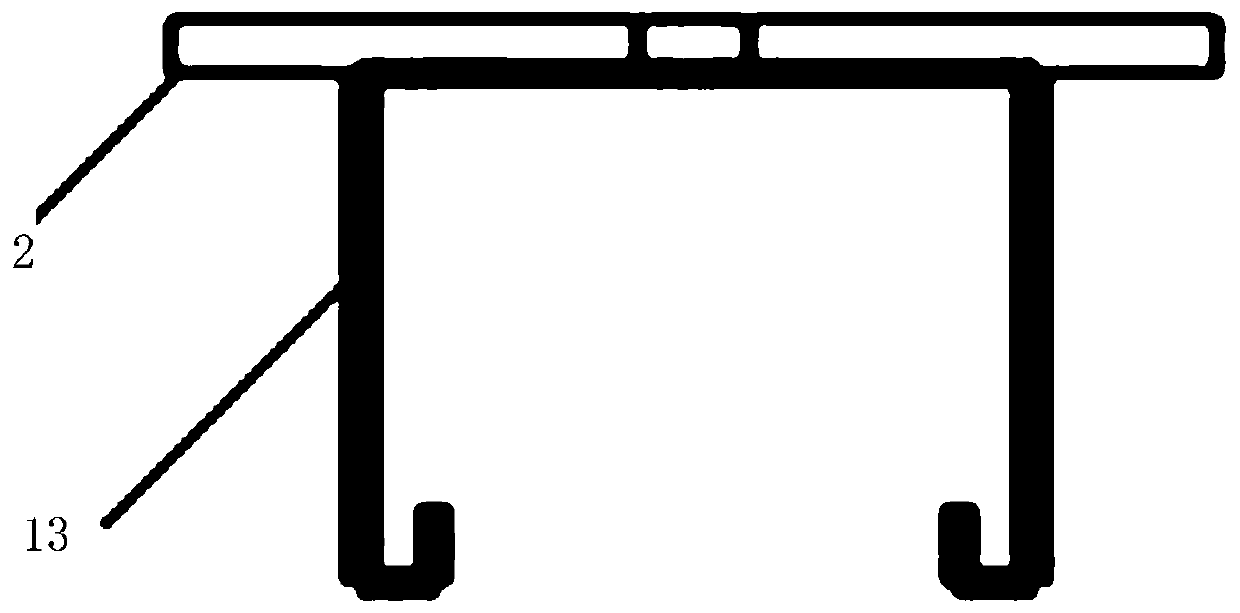
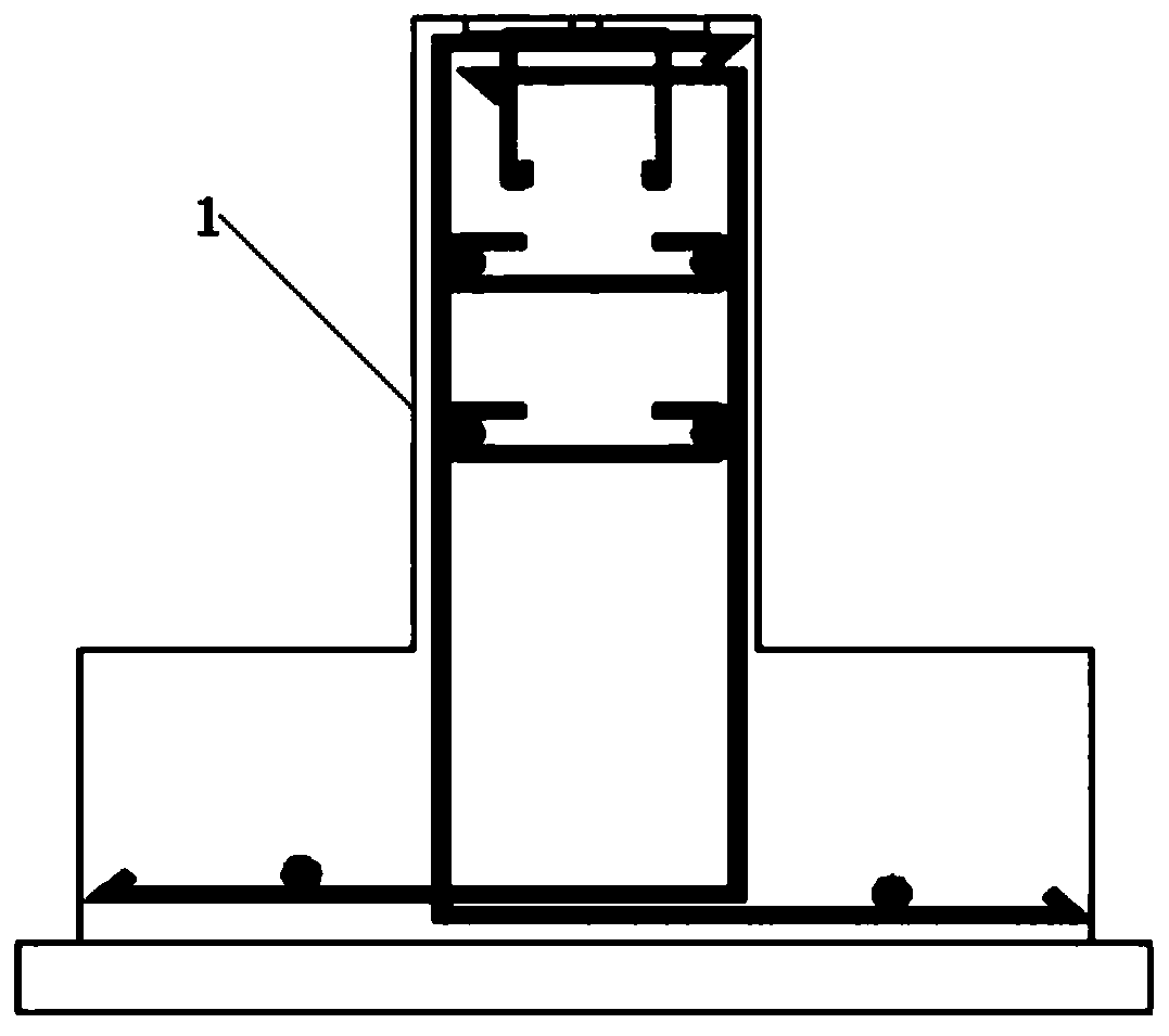
[0054] according to figure 1 , figure 2 and image 3 The steel structure beam type sliding staircase shown differs from the first embodiment in that the limiting sliding device includes embedded parts 2, embedded bolts 3, steel plates 4 and anchoring steel bars 13; the embedded parts 2 Pre-buried on the beam-type staircase foundation 1, the anchor steel bar 13 is connected to the lower surface of the embedded part 2; the steel plate 4 is connected to the upper surface of the embedded part 2; the center of the embedded part 2 and the steel plate 4 are respectively provided with reserved bolt holes; the embedded bolts 3 are connected in the reserved bolt holes.

[0055] In actual use, the steel plate 4 is welded to the ladder beam 6 of the bottom frame of the structure, and the steel plate 4 is connected with the embedded bolt 3 . The limit sliding device adopts this technical solution, which can effectively release the displacement under the action of the earthquake, so tha...

Embodiment 3

[0057] according to figure 1 , figure 2 and image 3 The steel structure beam type sliding staircase shown differs from the second embodiment in that the anchoring steel bar 13 is 2Φ8.

[0058] Further, the connection between the embedded part 2 and the anchoring steel bar 13 is welded.

[0059] Further, the embedded parts 2 are buried along the length of the steps.

[0060] In actual use, the anchoring steel bar 13 adopts 2Φ8, which can effectively anchor the embedded steel plate in the underlying foundation, and effectively transmit the frictional force generated by the displacement of the beam staircase.

[0061] The connection between the embedded part 2 and the anchoring steel bar 13 is welded; the steel plate 4 is connected with the embedded part 2 by the limited embedded bolt 3, and the bolt holes, especially the oval bolt holes, are helpful for effective Release displacement.

[0062] In actual use, the steel plate 4 and the steel plate at the bottom of the beam ...


PUM


Abstract

The invention belongs to the technical field of design of steel structural buildings, and particularly relates to a steel structural beam type sliding stair and a construction method. The steel structural beam type sliding stair is formed by a stair base, a limit sliding device, a bottom frame beam and a structural frame beam which is provided with lifting lugs, a double-sleeve limit connector anda rubber pin shaft connecting part; the limit sliding device is connected to the beam type stair base; the lower part of a stair beam is connected with the beam type stair base through the limit sliding device; and a stair beam which is not at the bottom is detachably connected with the structural frame beam which is provided with the lifting lugs, the double-sleeve limit connector and the rubberpin shaft connecting part. According to the steel structural beam type sliding stair and the construction method, the risk that a staircase is damaged before a main structural body under the workingcondition of earthquake can be effectively reduced, workload of field welding is reduced, a design process is simplified, construction efficiency is increased, and the use structure is relatively safeand reliable.

Description

technical field [0001] The invention belongs to the technical field of steel structure buildings, in particular to a steel structure beam type sliding staircase and its construction method. Background technique [0002] With the increase of steel structure buildings, more and more multi-storey and high-rise steel structure buildings appear in our lives. However, the design of steel structure stairs has always troubled structural designers. Conventional beam-type steel structure stairs usually use welding methods to connect with the main structure. Rigid connection, this method has the following disadvantages: [0003] 1. The force of the joint area is complex. The joints connected by welding not only transmit vertical shear force, but also transmit large joint bending moment under the action of earthquake force. The traditional welded connection will cause the connection part of the beam stair joint to bear a large bending moment before the main body of the structure is des...

Claims


Application Information

Patent Timeline
Patent Type & Authority Applications(China)
IPC IPC(8): E04F11/02E04F11/022
CPCE04F11/02E04F11/022
Inventor 李喆任兴文郭明马永宁郭亮刘小平朱利捷李剑钊赵玉慧杨丽周晓亮闵祥兵
Owner XIAN CHANGQING TECH ENG
Why Eureka
Try Eureka