Heat accumulation type radiant tube burner

A regenerative radiant tube and radiant tube technology, which can be applied to burners, combustion methods, combustion types, etc., can solve problems such as large nitrogen oxide emissions, unfavorable environmental protection, and non-compliance with emission standards.

Pending Publication Date: 2020-07-17
SHOUGANG ZHIXIN QIAN AN ELECTROMAGNETIC MATERIALS CO LTD
View PDF8 Cites 1 Cited by
  • Summary
  • Abstract
  • Description
  • Claims
  • Application Information

AI Technical Summary

Problems solved by technology

[0004] The embodiment of the present invention provides a regenerative radiant tube burner, which solves the technical problems in the prior art that the reg

Method used


Image

  • Heat accumulation type radiant tube burner
  • Heat accumulation type radiant tube burner
  • Heat accumulation type radiant tube burner

Examples


Embodiment 1

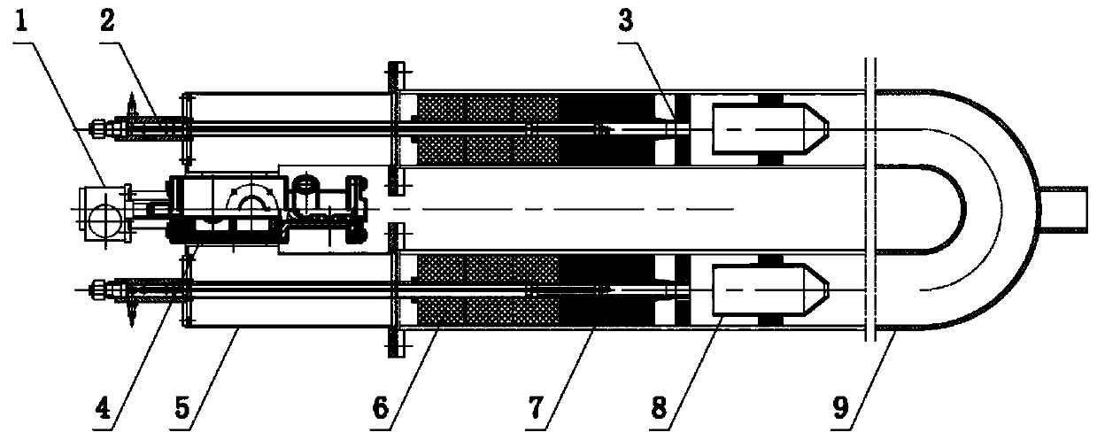
[0030] figure 1 It is a structural schematic diagram of a regenerative radiant tube burner according to an embodiment of the present invention, please refer to figure 1 , a regenerative radiant tube burner provided by an embodiment of the present invention, the regenerative radiant tube burner includes: a cylinder 1, a reversing valve 4, an air cavity 5, an ignition assembly 2, a heat storage body 6, a jet Disk 3, radiant tube 9, combustion cylinder 8.

[0031] The cylinder 1 is connected with a reversing valve 4, and the cylinder 1 drives the reversing valve 4 to control the gas direction; the reversing valve 4 has an air input end, an exhaust gas output end, and two reversing ports, and the reversing valve 4 The air input end of the reversing valve 4 can be selectively connected with one of the two reversing ports of the reversing valve 4 .

[0032] Specifically, the reversing valve 4 can rotate 90 degrees, and the cylinder 1 pushes the cylinder to move by compression, gen...


PUM

PropertyMeasurementUnit
Diameteraaaaaaaaaa
Diameteraaaaaaaaaa
Diameteraaaaaaaaaa

Abstract

The invention provides a heat accumulation type radiant tube burner. The heat accumulation type radiant tube burner comprises an air cylinder, a reversing valve, air cavities, a radiating pipe, ignition assemblies, heat accumulators, jet discs and combustion cylinders, wherein the reversing valve is connected with the air cylinder to control the air flow direction, the air cavities are connected with the reversing valve, the radiating pipe is connected with the air cavities and comprises two opposite cavities and a connecting cavity, one ends of the two cavities are respectively connected withthe air cavities, and the other ends of the two cavities communicate through the connecting cavity; and one end of each air cavity is provided with the ignition assembly, the heat accumulator, the jet disc and the combustion cylinder, and the heat accumulators, the jet discs and the combustion cylinders are sequentially arranged in the corresponding cavities according to the direction from one ends of the cavities to the other ends. The heat accumulation type radiant tube burner solves the technical problems that the nitrogen oxide discharge amount of a heat accumulation type radiant tube burner is large, and the discharge standard is not met. The heat accumulation type radiant tube burner achieves the technical effects of realizing grading mixing of air and coal gas, achieving grading combustion, avoiding the occurrence of local high-temperature areas, effectively reducing the generation of nitrogen oxides and meeting the national emission requirements.

Description

technical field [0001] The invention relates to the technical field of regenerative radiant tube burners, in particular to a regenerative radiant tube burner. Background technique [0002] Regenerative combustion technology is a technology that burns under high-temperature and low-oxygen air conditions. The main point of its working principle is that the regenerator as a heat carrier is periodically heated by high-temperature gas, and releases heat to low-temperature gas to realize heat transfer. transfer. It can improve energy utilization, especially the rational use of low-calorific-value fuels, which not only reduces pollutant emissions, but also saves energy. It has become an advanced technology that meets current resource and environmental requirements. At present, the domestic regenerative combustion technology is effective in steelmaking roasters, hot rolling furnaces and other processes. However, for high calorific value gas and applications in small combustion spac...

Claims


Application Information

Patent Timeline
IPC IPC(8): F23D14/02F23D14/46F23D14/48F23D14/64
CPCF23D14/02F23D14/46F23D14/48F23D14/64
Inventor 李立董文亮于浩淼汤小超谢宇刘磊马家骥
Owner SHOUGANG ZHIXIN QIAN AN ELECTROMAGNETIC MATERIALS CO LTD
Why Eureka
Try Eureka