
Plasma display screen of PDP discharge electrode

A plasma display and discharge electrode technology, applied in discharge tubes, gas-filled discharge tubes, circuits, etc., can solve problems such as internal air expansion, electrode heating, glass breakage, etc., to expand space, increase speed, and prevent equipment damage Effect

Inactive Publication Date: 2020-07-17
吴雪群
View PDF0 Cites 0 Cited by
  • Summary
  • Abstract
  • Description
  • Claims
  • Application Information

AI Technical Summary

Problems solved by technology

[0003] When the existing plasma display screen is in use, the internal electrode heats up, and the interior is in a vacuum-sealed state. If the heat is severe, the internal air will expand and the glass will break.

Method used

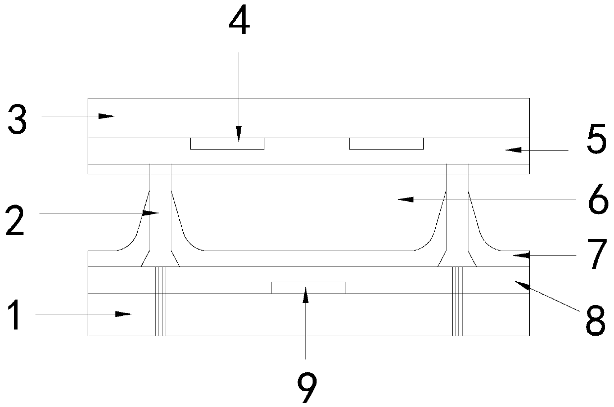
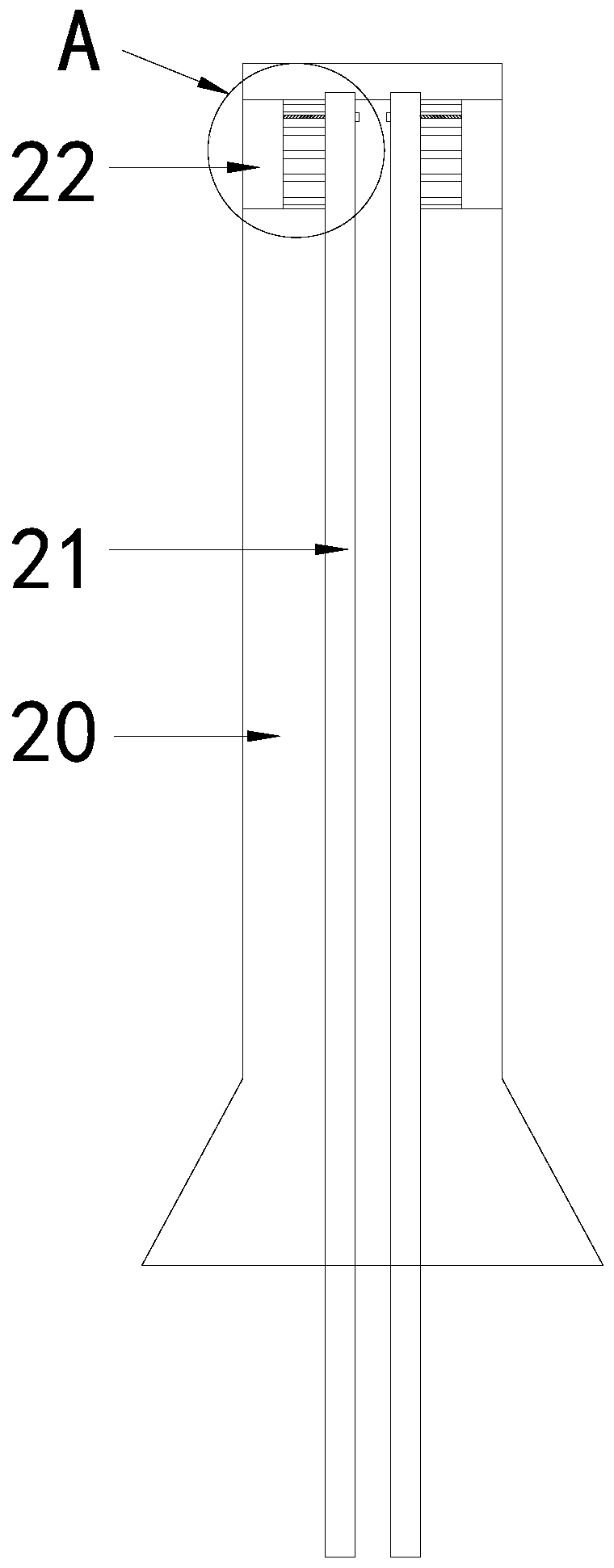
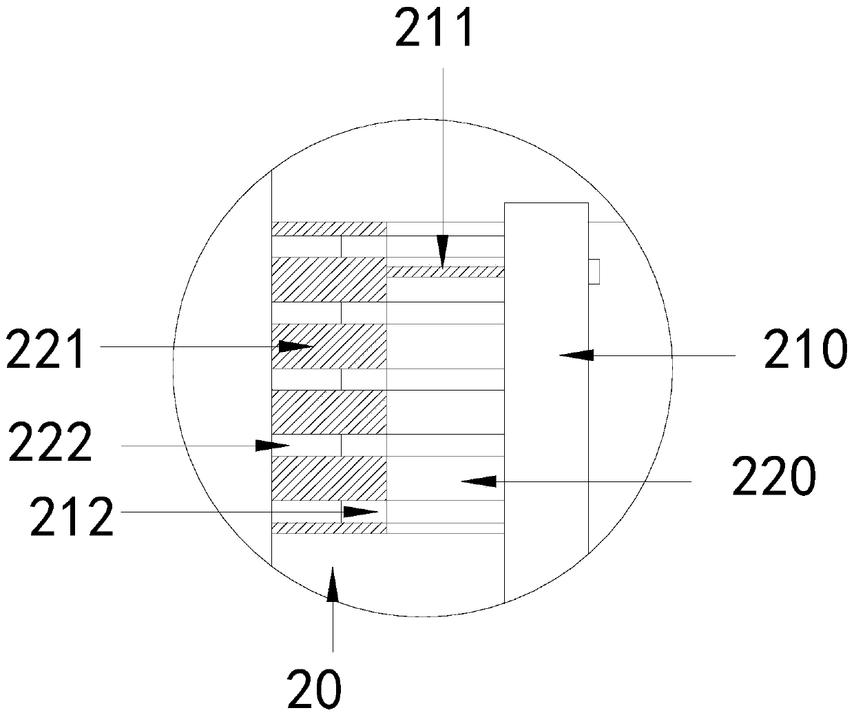

Image

  • Plasma display screen of PDP discharge electrode
  • Plasma display screen of PDP discharge electrode
  • Plasma display screen of PDP discharge electrode

Examples


Embodiment 1

[0027] see Figure 1-5 , the present invention provides a PDP discharge electrode plasma display screen technical scheme: its structure includes a back glass 1, a barrier 2, a front glass 3, a transparent electrode 4, a phosphor 5, an addressing electrode 6, the back glass 1 and the front The glass 3 is parallel, the back glass 1 is provided with phosphors 5 and separated by a barrier 2, the barrier 2 is connected between the front glass 3 and the back glass 1, and the front glass 3 is provided with a transparent electrode 4 , the back glass 1 is provided with an addressing electrode 6, and the barrier 2 includes a main body 20, a cooling structure 21, and a movable structure 22. One end of the main body 20 close to the front glass 3 is provided with movable structures 22 on both sides, so The cooling structure 21 is arranged in the middle of the main body 20 , the movable structure 22 includes a movable slot 220 and a moving block 221 , the movable slot 220 is arranged at one...

Embodiment 2

[0030] see Figure 1-5 , the present invention provides a PDP discharge electrode plasma display screen technical scheme: its structure includes a back glass 1, a barrier 2, a front glass 3, a transparent electrode 4, a phosphor 5, an addressing electrode 6, the back glass 1 and the front The glass 3 is parallel, the back glass 1 is provided with phosphors 5 and separated by a barrier 2, the barrier 2 is connected between the front glass 3 and the back glass 1, and the front glass 3 is provided with a transparent electrode 4 , the back glass 1 is provided with an addressing electrode 6, and the barrier 2 includes a main body 20, a cooling structure 21, and a movable structure 22. One end of the main body 20 close to the front glass 3 is provided with movable structures 22 on both sides, so The cooling structure 21 is arranged in the middle of the main body 20 , the movable structure 22 includes a movable slot 220 and a moving block 221 , the movable slot 220 is arranged at one...


PUM


Abstract

The invention discloses a plasma display screen of a PDP discharge electrode. The structure of the plasma display screen comprises back glass, a barrier wall, front glass, a transparent electrode, fluorescent powder and an addressing electrode. The back glass is parallel to the front glass; fluorescent powder is arranged on the back glass and is separated by the barrier wall; the barrier wall is connected between the front glass and the back glass; a transparent electrode is arranged in the front glass; the addressing electrode is arranged in the back glass; the barrier wall comprises a body,a cooling structure and movable structures. The movable structures are arranged on the two sides of the end, close to front glass, of the body. The cooling structure is arranged in the middle of the body. The plasma display screen has the beneficial effects that cooling is conducted through heat exchange between external cold air and the interior of the plasma display screen, rapid air draft can be conducted through the air draft structure when the temperature is high, the instantaneous cooling speed is increased, the movable block can move so that the internal space can be enlarged, and damage to the device due to air expansion is prevented.

Description

technical field [0001] The invention relates to the field of PDP plasma flat display screen, in particular to a plasma display screen of PDP discharge electrodes. Background technique [0002] The ion display panel is a vacuum chamber that uses He+Xe, Ne+Xe, He+Ne+Xe or He+Ne+Kr+Xe and other inert mixed gases to generate vacuum ultraviolet rays of about 147nm, so that the phosphor emits light to achieve our Visually perceptible text and images. [0003] When the existing plasma display screen is in use, the internal electrodes generate heat, and the interior is in a vacuum-sealed state. Serious heat generation can easily expand the internal air and cause the glass to break. SUMMARY OF THE INVENTION [0004] The main purpose of the present invention is to overcome the deficiencies of the prior art and provide a plasma display screen with a PDP discharge electrode. [0005] The present invention adopts the following technical scheme to realize: a plasma display screen of P...

Claims


Application Information

Patent Timeline
Patent Type & Authority Applications(China)
IPC IPC(8): H01J11/20H01J11/36H01J17/16H01J17/28
CPCH01J11/20H01J11/36H01J17/16H01J17/28H01J2211/36H01J2211/66
Inventor 吴雪群
Owner 吴雪群
Learn More