Dielectric resonator, dielectric filter, transceiver and base station

A dielectric resonator and dielectric filter technology, applied in the field of dielectric filters, transceivers, base stations, and dielectric resonators, can solve the problems of uncontrollable errors, increased short-circuit risk, small spacing, etc., and achieve high coupling and low loss. performance, reduce volume, and improve the effect of coupling energy

Inactive Publication Date: 2020-07-17
ANHUI TATFOOK TECH CO LTD
View PDF4 Cites 4 Cited by
  • Summary
  • Abstract
  • Description
  • Claims
  • Application Information

AI Technical Summary

Problems solved by technology

In order to achieve the purpose of capacitive coupling, the traditional dielectric waveguide filter usually adopts the following two forms: 1. The deep hole form is used to control the capacitive coupling bandwidth by adjusting the distance between the inner wall of the hole depth and the surface of the dielectric waveguide filter. The smaller the spacing, the narrower the capacitive coupling bandwidth. Therefore, to realize the adjustment of the narrow capacitive coupling bandwidth, the spacing will be quite small, and the problem of puncture is prone to occur during the production process, which increases the difficulty of production debugging; In the form of a through hole, a closed ring concentric with the through hole is arranged in the circumferential direction of the through hole. By adjusting the width of the ring, the narrower the width, the narrower the capacitive coupling bandwidth, thus, to achieve narrow capacitive coupling Bandwidth, the distance between the outer diameter and inner diameter of the ring will be quite small, resulting in uncontrollable errors in the production and debugging process, and also increasing the risk of short circuit
Therefore, the capacitive coupling structure of the traditional dielectric waveguide filter is difficult to produce and debug, which is not conducive to mass production

Method used


Image

  • Dielectric resonator, dielectric filter, transceiver and base station
  • Dielectric resonator, dielectric filter, transceiver and base station
  • Dielectric resonator, dielectric filter, transceiver and base station

Examples


Embodiment Construction

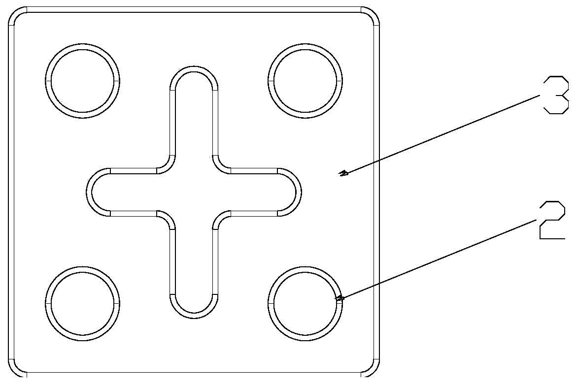
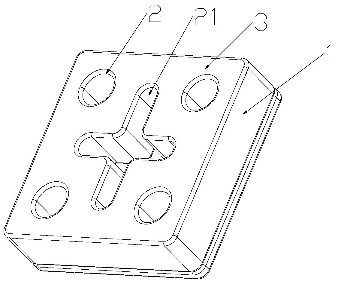
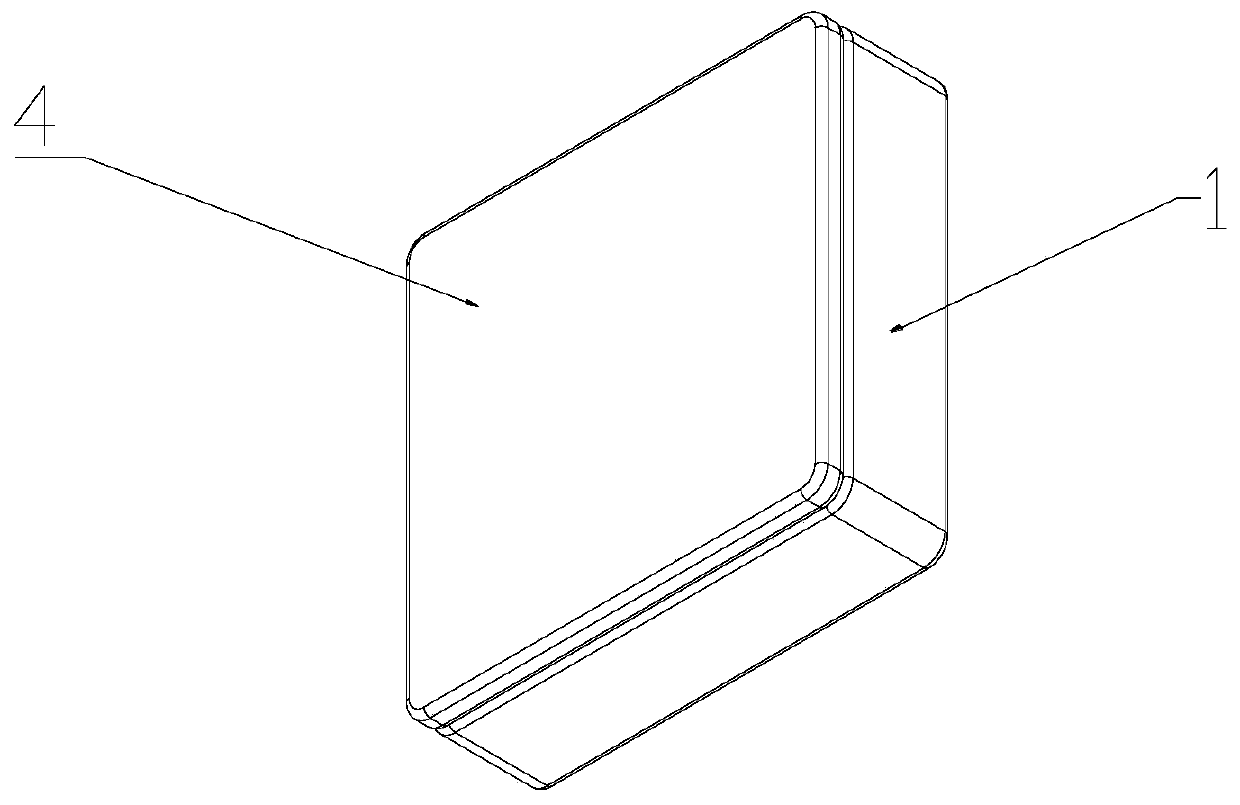
[0024] Below in conjunction with the appendix of the present invention Figure 1~3 , clearly and completely describe the technical solutions in the embodiments of the present invention, obviously, the described embodiments are only some of the embodiments of the present invention, not all of them. Based on the embodiments of the present invention, all other implementations can be obtained by those skilled in the art without making creative efforts.

[0025] In the description of the present invention, it should be understood that the terms "counterclockwise", "clockwise", "longitudinal", "transverse", "upper", "lower", "front", "rear", "left", The orientation or positional relationship indicated by "right", "vertical", "horizontal", "top", "bottom", "inner", "outer", etc. is based on the orientation or positional relationship shown in the drawings, and is only for the purpose of It is convenient to describe the present invention, but does not indicate or imply that the device...


PUM


Abstract

The invention relates to the technical field of dielectric filters, and aims to provide a dielectric resonator, a dielectric filter, a transceiver and a base station. The dielectric resonator comprises a dielectric single cavity, the dielectric single cavity comprises a first surface and a second surface which are opposite to each other, the first surface is provided with a first blind hole, and the bottom of the first blind hole is not provided with a metal layer. The dielectric resonator has the advantages of being narrow in capacitive coupling bandwidth, being easy to produce and debug, being free of short circuit risks and the like, and is suitable for mass production.

Description

technical field [0001] The invention relates to the field of dielectric filters, in particular to a dielectric resonator, a dielectric filter, a transceiver and a base station. Background technique [0002] A filter is a frequency-selective device that allows specific frequency components in a signal to pass while greatly attenuating other frequency components. The waveguide filter is one of the filters used in communication systems, while the traditional waveguide filter is a metal cavity structure with air in the middle, and the edge of the metal material plays the role of electromagnetic shielding and structural support. The filter using this method has a higher Q value, but its volume and weight are relatively large, which is not conducive to installation and transportation. With the development of communication systems, filters are required to have the characteristics of low insertion loss, high rejection, high power withstand, low cost, and miniaturization. Therefore...

Claims


Application Information

Patent Timeline
Patent Type & Authority Applications(China)
IPC IPC(8): H01P7/10H01P7/06H01P1/20H01P1/208
CPCH01P1/2002H01P1/208H01P7/06H01P7/10
Inventor 童恩东王细冬
Owner ANHUI TATFOOK TECH CO LTD
Why Eureka
Try Eureka