Time-to-digital converter

A time-to-digital converter and counter technology, applied in the field of time-to-digital converters, can solve the problems of high risk, error correction algorithm can not work as expected, difficult to meet and so on

Active Publication Date: 2020-07-17
HUAWEI INT
View PDF10 Cites 1 Cited by
  • Summary
  • Abstract
  • Description
  • Claims
  • Application Information

AI Technical Summary

Problems solved by technology

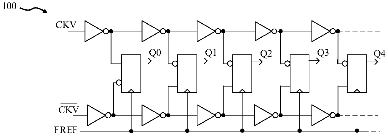
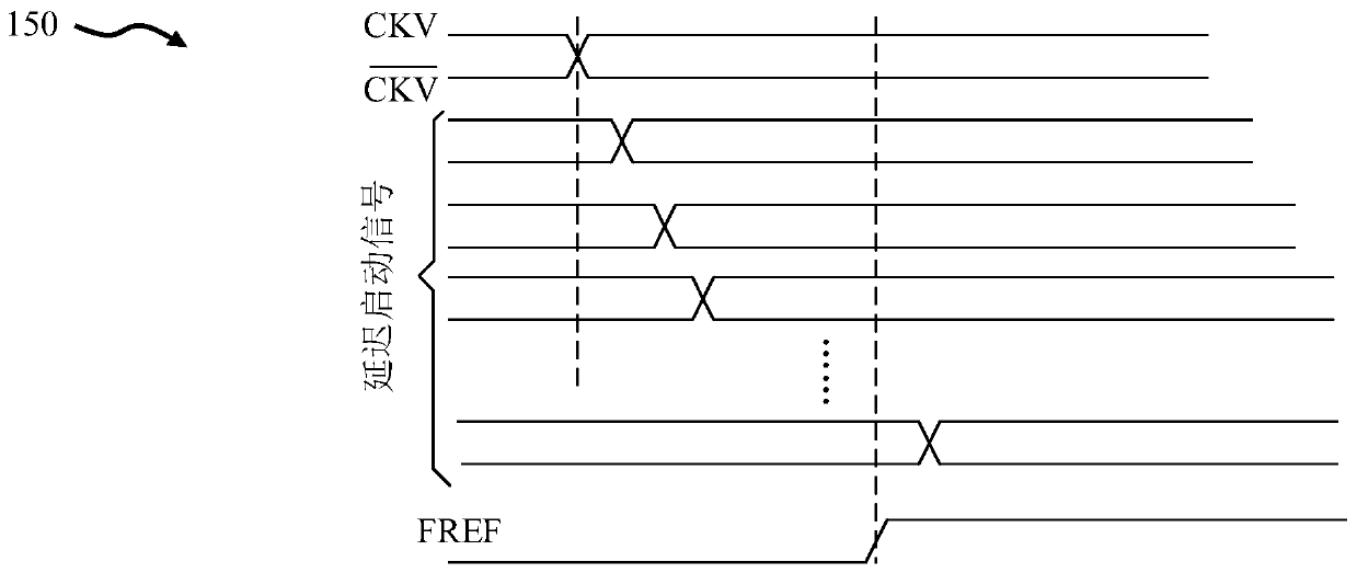
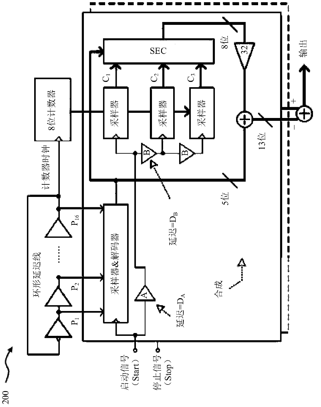
However, the problem with the RO based TDC200 is that since the start and stop signals are not synchronized with the counter clock, the sampled counter output can be wrong
In addition, certain assumptions are made for the delay design of the RO-based TDC 200, which are difficult to meet in actual production
When process-voltage-temperature (PVT) variations and equipment mismatches occur, the actual delay

Method used


Image

  • Time-to-digital converter
  • Time-to-digital converter
  • Time-to-digital converter

Examples


Embodiment Construction

[0034] image 3 is a schematic diagram of the proposed time-to-digital converter (TDC) 300 according to an embodiment. TDC 300 may also be referred to as cyclic TDC 300 . In general, TDC 300 includes a (presettable) ring oscillator module 302 and a digital error correction module 304 . The ring oscillator module 302 is used to receive sampling signals, addressing signals and preset signals. The ring oscillator module 302 includes: a plurality of inverters 3024 (arranged in sequence in N stages, wherein "N" represents the number of stages , for example, "N" can be 15) the ring oscillator 3022; the phase sampler 3026 is used for, when receiving the sampling signal, the phase signal generated by the plurality of inverters 3024 of the ring oscillator 3022 (ie exist image 3 Respectively represented as "Vout", "Vout", ..., "Vout ”) to sample to generate the first output signal (i.e. at image 3 denoted as "frac" in ); a counter clock generator 3028 (implemented by a conventional...


PUM


Abstract

A time-to-digital converter (TDC) (300) is disclosed, which comprises a ring oscillator module (302) and a digital error correction module (304). The ring oscillator module is configured to receive asampling signal, an addressing signal, and a preset signal, and includes: a ring oscillator (3022) arranged with a plurality of inverters (3024); a phase sampler (3028) configured to sample phase signals generated by the inverters of the ring oscillator for generating a first output signal, on receipt of the sampling signal; a counter clock generator (3028) configured to generate first and secondclock signals, based on receipt of the sampling signal and respective phase signals generated by the first and last inverters of the ring oscillator; first and second counters (3030, 3032) configuredto respectively generate first and second counter output signals, based on receipt of the first and second clock signals respectively: and a data sampler (3034) configured to sample the first and second counter output signals to respectively generate second and third output signals. The digital error correction module is arranged to process the first, second and third output signals for generatinga digital signal representative of a time difference between receipt of a start signal and receipt of a stop signal by the TDC.

Description

technical field [0001] The present invention relates to a time-to-digital converter (time-to-digital converter, TDC). Background technique [0002] Time-to-digital converters (TDCs) have been used extensively for over 20 years in numerous applications requiring precise time interval measurements. Some examples of applications include particle and high energy physics, biomedical imaging such as positron emission tomography (PET), and various time-of-flight (ToF) measurements. With the development of complementary metal oxide semiconductor (CMOS) technology, the all-digital phase-locked loop (all-digital phase-locked loop, ADPLL) of the digital communication system also adopts TDC. By converting time or phase information into digital codes, TDC enables the evolution of PLLs to an all-digital domain, replacing traditional analog PLLs. Another emerging application area of ​​TDC is TDC-based analog-to-digital converter (analog-to-digital converter, ADC). Although requirements ...

Claims


Application Information

Patent Timeline
IPC IPC(8): G04F10/00
CPCG04F10/005H03K3/0315H03L7/085
Inventor 袁超于锐陈雪松刘苏鹏杨腾智
Owner HUAWEI INT
Why Eureka
Try Eureka