
Hydraulic vibration device

A technology of hydraulic vibration and vibration source, which is applied in the direction of fluid pressure actuators, electromechanical devices, fluid pressure actuator system components, etc., can solve the problems of high failure rate and inability to adjust, and achieve low failure rate, strong applicability, High safety effect

Inactive Publication Date: 2020-07-21
HENAN TIEFULAI EQUIP MFG CO LTD
View PDF6 Cites 0 Cited by
  • Summary
  • Abstract
  • Description
  • Claims
  • Application Information

AI Technical Summary

Problems solved by technology

In addition, the device is mainly driven and controlled by the hydraulic system, which can be used in ordinary and special environments, and has high safety in special environments; through the control of the throttle valve, vibration control can be realized without stopping the machine. The stepless adjustment of source excitation force and vibration frequency effectively solves the problems of traditional vibration motors that have potential safety hazards, cannot be adjusted in the power-on state, and have a high failure rate in special environments

Method used


Image

  • Hydraulic vibration device
  • Hydraulic vibration device
  • Hydraulic vibration device

Examples


Embodiment Construction

[0033] The present invention will be further described now in conjunction with accompanying drawing.

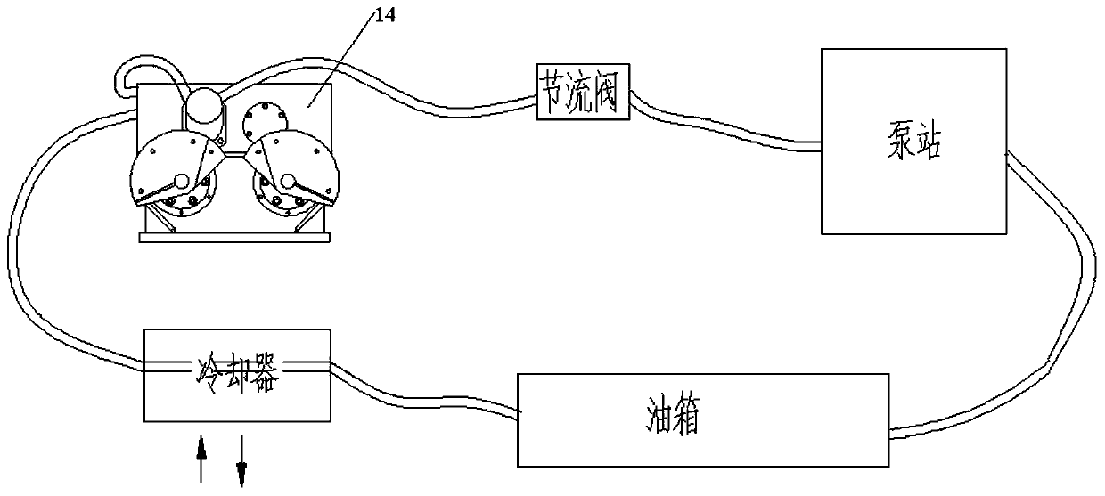
[0034] The present invention also provides a hydraulic vibrating device 14, which uses hydraulic drive technology to drive the eccentric block through a hydraulic motor to generate an exciting force, and at the same time, after hydraulic oil is introduced into the vibration source shell, it enters the cooling system through a hydraulic pipeline, and realizes While lubricating the internal transmission gear, it cools the vibration source gear mechanism. Through the adjustment of the hydraulic valve, the stepless speed change can be realized without stopping the machine, which greatly improves the safety and work efficiency of the equipment.

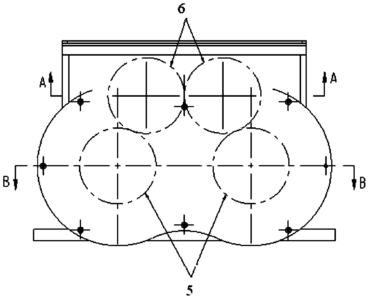
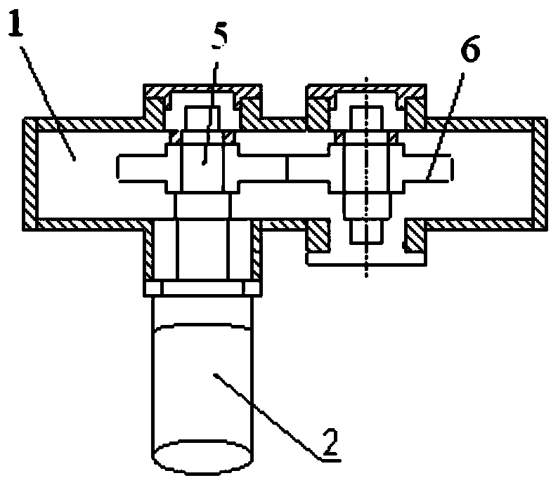
[0035] Such as figure 2 , 3 As shown in and 4, the hydraulic vibration device includes: a vibration source 1 and a power source 2, the power source 2 is used to generate power, and is transmitted to the polarization block of the vibrat...


PUM


Abstract

The invention relates to a hydraulic vibration device. The hydraulic vibration device comprises a vibration source (1) and a power source (2), wherein the power source (2) is used for producing powerand transmitting the power to a polarization block of the vibration source (1) to produce excitation force; the power source (2) adopts a hydraulic power source. According to the hydraulic vibration device disclosed by the invention, through adjusting the flow of hydraulic oil, the power source is controlled in real time; the polarization block is driven by a hydraulic motor to produce the excitation force, and besides, after being introduced in a vibration source housing, the hydraulic oil enters a cooling system through a hydraulic pipeline, so that an inner transmission gear is lubricated,and besides, a gear mechanism in the vibration source can be cooled; and through adjusting the hydraulic valve, stepless speed change can be realized under the condition that the machine is not stopped, and the safety and the working efficiency of the equipment are greatly improved.

Description

technical field [0001] The invention belongs to the technical field of vibration motors, and in particular relates to a hydraulic vibration device. Background technique [0002] The vibration motor installs a set of adjustable eccentric blocks at both ends of the rotor shaft, and uses the centrifugal force generated by the high-speed rotation of the shaft and eccentric blocks to obtain the exciting force. The vibration motor is an excitation source that combines the power source and the vibration source. The vibration motor has a large invalid vibration mass and cannot be used in an environment with special requirements. Vibration motors cannot adjust the exciting force, amplitude and vibration frequency in the power-on state. [0003] At present, vibration machines are generally driven by vibration motors, which have certain advantages in relatively simple equipment and low power ranges. But existing vibrating motor kind is a lot, no matter be horizontal or vertical, all ...

Claims


Application Information

Patent Timeline
Patent Type & Authority Applications(China)
IPC IPC(8): F15B11/08F15B13/02F15B13/04F15B21/0423H02K7/116
CPCF15B11/08F15B13/023F15B13/04F15B21/042H02K7/116
Inventor 武国胜徐云辉高彬彬刘亚晓陈超飞崔芳芳
Owner HENAN TIEFULAI EQUIP MFG CO LTD
Learn More