Driving method and driving circuit of ultrasonic atomizer
A driving method and driving circuit technology, applied in noise suppression, instruments, simulators, etc., can solve the problems of increasing the size of the humidifier, having no practical atomization effect, and dropping the water level, so as to improve the depth of the atomization water level, Reduce energy consumption and cost, reduce the effect of height
- Summary
- Abstract
- Description
- Claims
- Application Information
AI Technical Summary
Problems solved by technology
Method used
Image

Examples
Embodiment 1
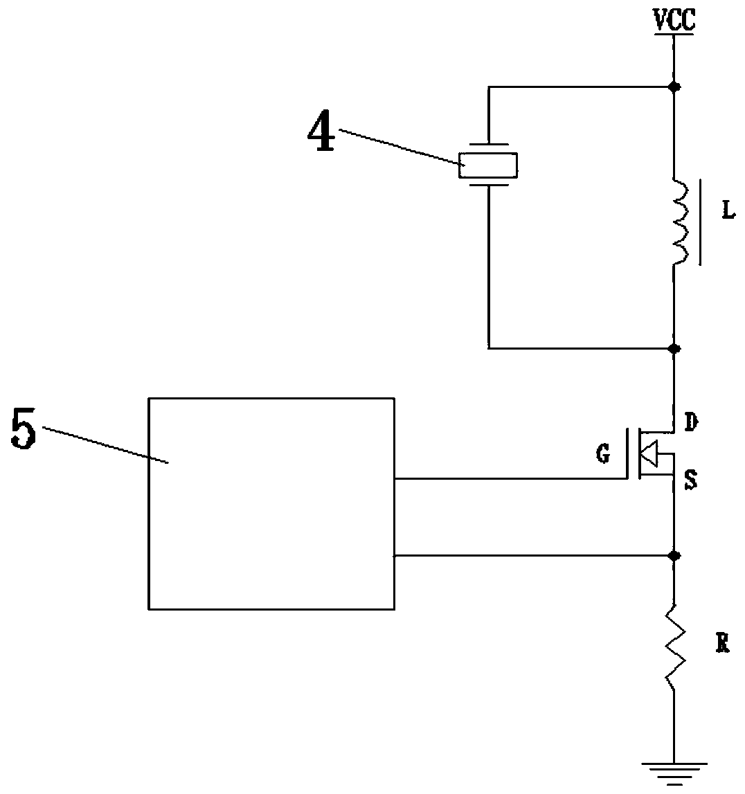
[0026] Example 1, such as figure 1 Shown is the schematic connection diagram of the ultrasonic atomizing sheet 4 and the drive circuit two-legged inductor L. The inductor L is a two-legged inductor with a set of coils inside. First, the VCC terminal is connected to the power supply, and the first leg of the inductor L 1. One end of the ultrasonic atomizing sheet 4 is connected to the VCC terminal respectively, the second leg of the inductor L is connected to the other end of the ultrasonic atomizing sheet 4 and the D pole of the MOS tube, and the control unit 5 is respectively connected to the G pole and the S pole of the MOS tube and the first end of the resistor R, and the second end of the resistor R is grounded.
Embodiment 2
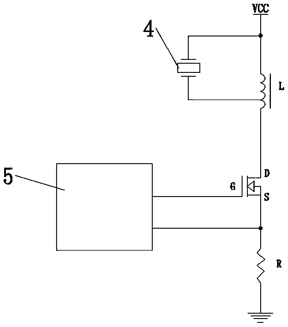
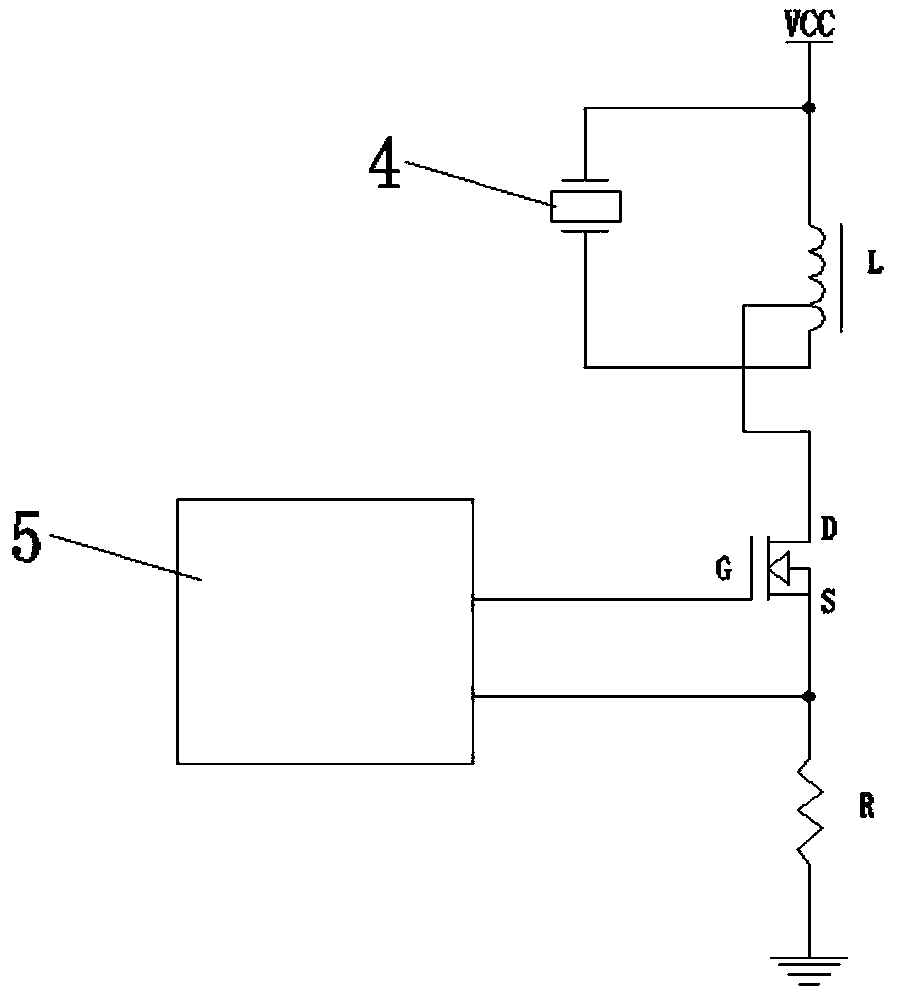
[0027] Example 2, such as Figure 2-5 As shown, the inductance L is a three-legged inductance, and two sets of coils are arranged inside it;
[0028] Among them, such as figure 2 , 3 As shown, one end of the ultrasonic atomizing sheet 4 and the first leg of the inductor L are respectively connected to the VCC terminal to access the power supply, and the second leg of the inductor L can be connected to the other end of the ultrasonic atomizing sheet 4 or the D pole of the MOS tube. The third leg of L can be connected with the other end of the ultrasonic atomizing sheet 4 or the D pole of the MOS tube. Specifically, as figure 2 As shown, when the second leg of the inductance L is connected to the D pole of the MOS tube, the third leg of the inductance L is connected to the other end of the ultrasonic atomizing sheet 4; image 3 As shown, when the third leg of the inductor L is connected to the D pole of the MOS tube, the second leg of the inductor L is connected to the oth...
Embodiment 3
[0030] Example 3, such as Image 6 As shown, the inductor L is a four-legged inductor, and two sets of coils are set inside it. First, the first leg of the inductor L is connected to the power supply from the VCC terminal, the second leg of the inductor L is connected to the D pole of the MOS tube, and the inductor L’s The third leg is connected to one end of the ultrasonic atomizing sheet 4, the fourth leg of the inductance L is connected to the other end of the ultrasonic atomizing sheet 4; the control unit 5 is connected to the G pole and the S pole of the MOS tube, and the resistor R The first end of the resistor R is connected to the S pole of the MOS tube, and the second end of the resistor R is grounded.
[0031] Working principle: The drive circuit is used in an ultrasonic atomizer (humidifier) and is connected to the ultrasonic atomizer 4. The control unit 5 provides an oscillation signal of a certain frequency to the G pole of the MOS tube, and passes the signal of...
PUM
 Abstract
Description
Claims
Application Information
 - R&D
- Intellectual Property
- Life Sciences
- Materials
- Tech Scout
- Unparalleled Data Quality
- Higher Quality Content
- 60% Fewer Hallucinations
Browse by: Latest US Patents, China's latest patents, Technical Efficacy Thesaurus, Application Domain, Technology Topic, Popular Technical Reports.
© 2025 PatSnap. All rights reserved.Legal|Privacy policy|Modern Slavery Act Transparency Statement|Sitemap|About US| Contact US: help@patsnap.com