Glass curtain wall with drainage structure and mounting method thereof

A glass curtain wall and drainage structure technology, applied in the direction of walls, building components, building structures, etc., can solve the problems of time-consuming, complicated, unfavorable fast installation of glass curtain walls, etc., and achieve the effect of avoiding inconvenience and saving time

Active Publication Date: 2020-07-24
广东汇赢模块化房屋科技有限公司
View PDF7 Cites 2 Cited by
  • Summary
  • Abstract
  • Description
  • Claims
  • Application Information

AI Technical Summary

Problems solved by technology

[0004] The above-mentioned existing technical solutions have the following defects: in the existing glass curtain wall, due to the construction technology of the connection between the glass plate and the column or beam or the cracks caused by the aging of the sealant, rainwater will enter the inner side of the glass curtain wall. Drain the accumulated water on the inside of the glass curtain wall, and the existing technology often uses pipeline drainage to drain rainwater. The construction process is: construction of the external wall drainage pipeline support external wall - drainage pipeline installation (plastic film protection) - wear Installation of wall pipes—plugging seams of pipes through walls (installation place)—handover to the civil engineering pipes for repairs and construction of exterior wall waterproof coating——cleaning of drainage pipes (removal of protective film) → removal of the outer frame, and the existing pipes can be known The construction of drainage is generally complicated and time-consuming, which is not conducive to the rapid installation of glass curtain walls, so it is necessary to improve the above-mentioned existing technologies

Method used


Image

  • Glass curtain wall with drainage structure and mounting method thereof
  • Glass curtain wall with drainage structure and mounting method thereof
  • Glass curtain wall with drainage structure and mounting method thereof

Examples


Embodiment Construction

[0051] The present invention will be described in further detail below in conjunction with the accompanying drawings.

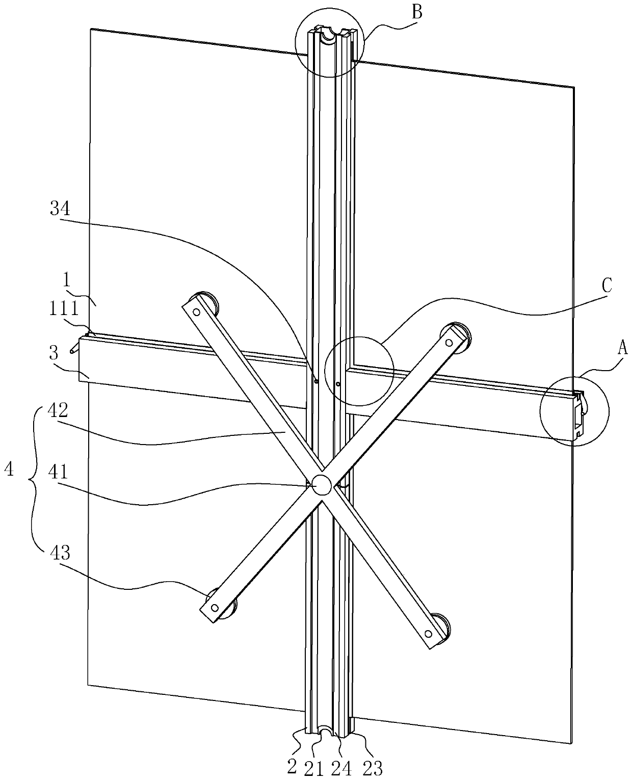
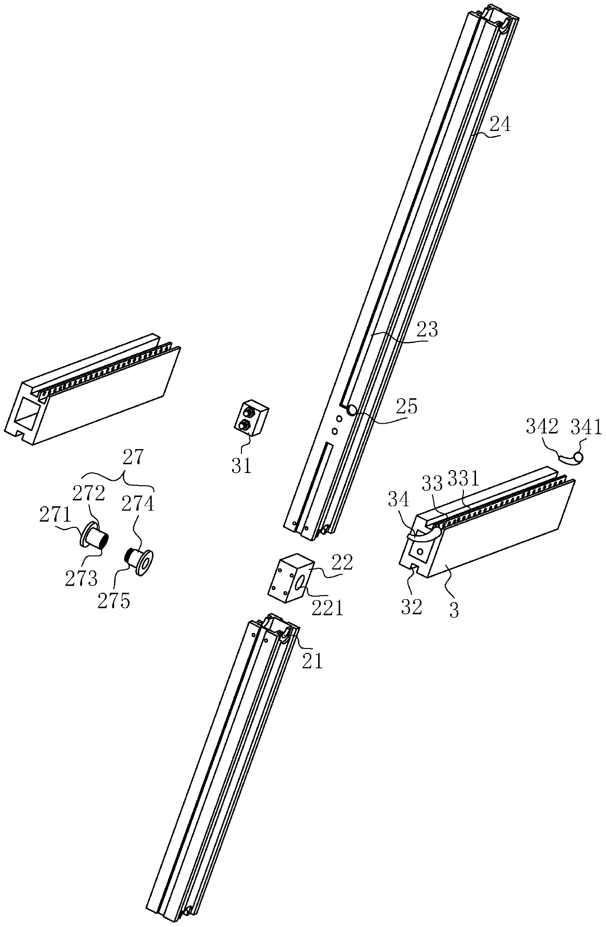
[0052] refer to figure 1 , is a glass curtain wall with a drainage structure and its installation method disclosed in the present invention, including a glass plate 1, a column 2 and a beam 3, wherein the end of the column 2 is plugged with another column 2 to realize the connection between the columns 2 , The column 2 and the beam 3 are fixedly connected by bolts; the glass plate 1 is embedded in the sides of the column 2 and the beam 3 . The installed glass plate 1 is clamped and fixed by the glass claws 4 and the fastening claws 5 .

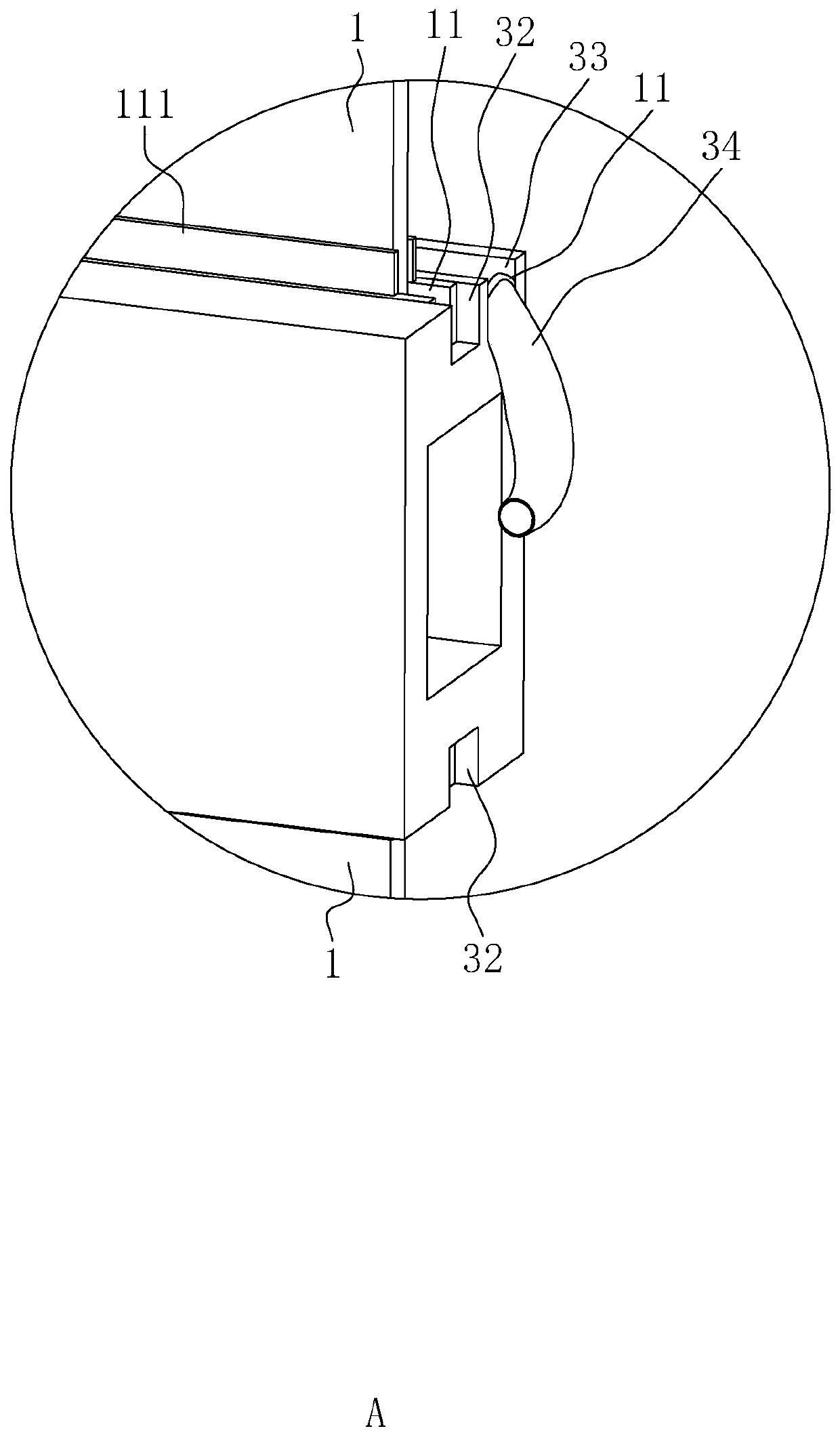
[0053] refer to figure 1 , figure 2 , the above beam 3 can be made of aluminum alloy, and the inside of the beam 3 is hollow. The opposite sides of the crossbeam 3 are provided with transverse limit grooves 32, the length direction of the transverse limit grooves 32 is parallel to the length direction of the crossbeam 3,...


PUM


Abstract

The invention relates to the technical field of glass curtain walls, in particular to a glass curtain wall with a drainage structure and a mounting method thereof. The glass curtain wall with the drainage structure comprises glass plates, stand columns and cross beams, the stand columns are connected through longitudinal insertion cores, and the stand columns and the cross beams are connected through transverse insertion cores; transverse limiting grooves are formed in the cross beams, longitudinal limiting grooves are formed in the stand columns, and the peripheral edges of the glass plates are clamped and fixed to the transverse limiting grooves and the longitudinal limiting grooves in a connected mode; waterproof sealing rubber strips are filled into the positions between the glass plates and the cross beams and between the glass plates and the stand columns, and the waterproof sealing rubber strips are bonded and fixed to the glass plates through silicone adhesives; transverse drainage grooves are formed in one sides of the cross beams, and openings of the transverse drainage grooves of the cross beams are connected with water guide nozzles; leading-in openings of the water guide nozzles are connected with the openings of the transverse drainage grooves, and leading-out openings of the water guide nozzles penetrate through the stand columns and are led out to the other sides of the glass plates; and the stand columns are provided with longitudinal drainage grooves used for draining water drained by the water guide nozzles. The glass curtain wall has the effects that theconstruction steps of extra pipeline drainage can be reduced, and rapid installation of the glass curtain wall is facilitated.

Description

technical field [0001] The invention relates to the technical field of glass curtain walls, in particular to a glass curtain wall with a drainage structure and an installation method thereof. Background technique [0002] At present, the box house is a kind of mobile and reusable construction product. The box room can be used for: 1. The high-end demand of the construction site for temporary construction products, such as the project manager's office, accommodation room, meeting room, etc.; some construction sites are limited by the site, and only box-type combined room products can be installed; 2. Houses for field operations, such as: field exploration and construction mobile offices, dormitories, etc.; 3. Emergency rooms, such as: military mobile command center, emergency mobile command center, disaster relief mobile command center, etc. The outer periphery of the box room is equipped with a glass curtain wall. Since the glass curtain wall can block most of the heat, the...

Claims


Application Information

Patent Timeline
Patent Type & Authority Applications(China)
IPC IPC(8): E04B2/96E04B1/684E04B1/70E04B2/88
CPCE04B1/6806E04B1/70E04B1/7046E04B2/885E04B2/96E04B2/965
Inventor 鲁赢
Owner 广东汇赢模块化房屋科技有限公司
Why Eureka
Try Eureka