

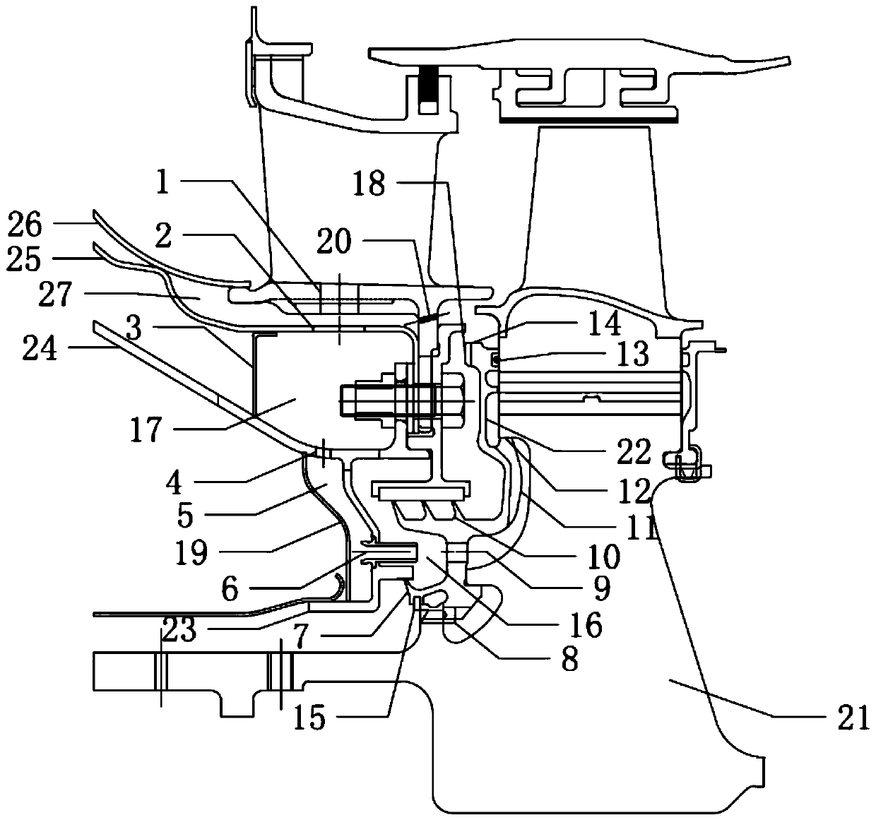
Engine turbine disc cavity structure with pre-rotation nozzle and flow guiding disc
A technology of pre-swirl nozzles and turbine discs, applied in engine components, machines/engines, mechanical equipment, etc., can solve the problems of affecting cooling and sealing effect, circumferential pressure fluctuation of main gas, temperature rise and pressure loss, etc. Achieve the effect of reducing mixing loss, improving sealing effect, and small working deformation
- Summary
- Abstract
- Description
- Claims
- Application Information
AI Technical Summary
Problems solved by technology
Method used
Image

Examples
Embodiment Construction
[0047] In order to make the objectives, technical solutions and advantages of the present invention clearer, the technical solutions in the embodiments of the present invention will be described in more detail below in conjunction with the drawings in the embodiments of the present invention. In the drawings, the same or similar reference numerals denote the same or similar elements or elements having the same or similar functions throughout. The described embodiments are some, but not all, embodiments of the invention. The embodiments described below by referring to the figures are exemplary and are intended to explain the present invention and should not be construed as limiting the present invention. Based on the embodiments of the present invention, all other embodiments obtained by persons of ordinary skill in the art without creative efforts fall within the protection scope of the present invention. The structure and technical solutions of the present invention will be ...
PUM
 Abstract
Description
Claims
Application Information