Seismic exploration gas explosion type seismic source bomb and using method thereof

A technology for seismic exploration and source bombs, which is applied in seismology, geophysical measurement, measurement devices, etc., can solve problems such as large power consumption, and achieve the effects of no power consumption, environmental friendliness, and convenient transportation.

Pending Publication Date: 2020-07-24
ENERGY RES INST OF SHANDONG ACAD OF SCI
View PDF0 Cites 0 Cited by
  • Summary
  • Abstract
  • Description
  • Claims
  • Application Information

AI Technical Summary

Problems solved by technology

However, the inventors found that this blasting method needs to consume a large amount of electric energy. If it is used as a seismic source bomb, the energy is usually from several hundred joules to hundreds of thousands of joules, and the exploration depth is from several meters to several thousand meters.

Method used


Image

  • Seismic exploration gas explosion type seismic source bomb and using method thereof

Examples


no. 1 example

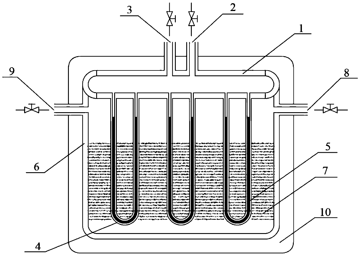
[0037] first embodiment ,refer to figure 1 , an example of a seismic exploration gas explosion type seismic source bomb designed by the present invention and its use method, including: a pressure vessel 1, a carbon dioxide filling port 2, a first exhaust port 3, a branch pipe 4, liquid carbon dioxide 5, a reaction vessel 6, quicklime 7. Water injection port 8, second exhaust port 9 and insulation layer 10.

[0038] The pressure vessel 1 (made of 304 stainless steel) is used as an inner cartridge case, on which a carbon dioxide filling port 2, a first exhaust port 3, and a branch pipe 4 are arranged. The branch pipe 4 communicates with the pressure vessel 1, and the branch pipe 4 is filled with liquid Carbon dioxide 5 is used as an explosive working medium; the branch pipe 4 is installed in a reaction vessel 6 (made of 304 stainless steel), and the reaction vessel 6 is used as an outer shell, filled with quicklime 7 as an energy storage working medium, and the quicklime 7 is ...

no. 2 example

[0043] second embodiment , the pressure vessel 1 is an annular pipeline, and the pipeline that forms the annular pipeline is a circular pipe, and each end of the carbon dioxide filling port 2 and the first exhaust port 3 is connected with the annular pipeline, and the carbon dioxide filling port 2 It is arranged side by side with the first exhaust port 3 , and the branch pipe 4 is arranged on the opposite side of the carbon dioxide filling port 2 and the first exhaust port 3 .

no. 3 example

[0044] third embodiment , the pressure vessel 1 is an annular pipe, the shape of the annular pipe is circular, and the pipes forming the annular pipe are square pipes, and the respective ends of the carbon dioxide filling port 2 and the first exhaust port 3 are connected with each other. The annular pipeline is connected, and the carbon dioxide filling port 2 and the first exhaust port 3 are arranged side by side, and the branch pipe 4 is arranged on the opposite side of the carbon dioxide filling port 2 and the first exhaust port 3 .


PUM


Abstract

The invention relates to the technical field of physical explosion source bombs, and in particular relates to a seismic exploration gas explosion source bomb and a using method thereof. According to the structure of the seismic source bomb, a pressure container is provided with a carbon dioxide filling port, a first exhaust port and a branch pipe, the branch pipe communicates with the pressure container, and liquid carbon dioxide is loaded in the branch pipe; the branch pipe is mounted in a reaction container, and the reaction container is filled with quicklime wrapping the branch pipe; a water injection port and a second exhaust port are both formed in the reaction container, the pressure container and the reaction container are wrapped in a heat preservation layer, and the pressure container and the reaction container form an inner cartridge case and an outer cartridge case of the seismic source bomb respectively; and valves are respectively arranged at ports, extending out of the heat preservation layer, of the carbon dioxide filling port, the first exhaust port, the water injection port and the second exhaust port. Carbon dioxide expansion serves as an explosion working medium,and hydration heating of water and quicklime is adopted for detonation, so that the detonation is simpler compared with electrified gas explosion, electric energy is not consumed, and the method is very suitable for field and underwater seismic prospecting operation.

Description

technical field [0001] The invention relates to the technical field of physical explosion seismic source bombs, in particular to a seismic exploration gas explosion type seismic source bomb and a method for using the same. Background technique [0002] The information disclosed in the Background of the Invention is only intended to increase the understanding of the general background of the invention, and is not necessarily to be taken as an acknowledgment or any form of suggestion that the information constitutes the prior art that is already known to those skilled in the art. [0003] Seismic prospecting is a major prospecting method in engineering exploration. Its principle is to artificially excite seismic waves on the surface. When propagating underground, the seismic waves will be reflected and refracted when encountering rock layers with different medium properties. The seismic waves are received by geophones in the well. The received seismic wave signal is related t...

Claims


Application Information

Patent Timeline
Patent Type & Authority Applications(China)
IPC IPC(8): G01V1/137
CPCG01V1/137
Inventor 江亚柯朱昭勖梁世强刘志刚贾磊吕明明段炼黄继凯
Owner ENERGY RES INST OF SHANDONG ACAD OF SCI
Why Eureka
Try Eureka