
Automatic machining equipment for ceramic ferrules

An automatic processing, ceramic ferrule technology, applied in the direction of light guide, optics, instruments, etc., can solve the problems of time-consuming, labor-intensive, manual operation, etc., and achieve the effect of stable pressing, high completion, and high accuracy.

Active Publication Date: 2020-07-24
深圳市前海中剑辰星科技有限公司
View PDF6 Cites 6 Cited by
  • Summary
  • Abstract
  • Description
  • Claims
  • Application Information

AI Technical Summary

Problems solved by technology

The current ceramic ferrule equipment is mostly semi-automatic equipment, and some of the processes require manual operation, which is time-consuming and labor-intensive.

Method used


Image

  • Automatic machining equipment for ceramic ferrules
  • Automatic machining equipment for ceramic ferrules
  • Automatic machining equipment for ceramic ferrules

Examples


Embodiment Construction

[0023] In order to facilitate the understanding of the present invention, the present invention will be described in more detail below in conjunction with the accompanying drawings and specific embodiments. Preferred embodiments of the invention are shown in the accompanying drawings. However, the present invention can be implemented in many different forms and is not limited to the embodiments described in this specification. On the contrary, these embodiments are provided to make the understanding of the disclosure of the present invention more thorough and comprehensive.

[0024] It should be noted that when an element is referred to as being “fixed” to another element, it can be directly on the other element or there can also be an intervening element. When an element is referred to as being "connected to" another element, it can be directly connected to the other element or intervening elements may also be present. The terms "fixed", "integrated", "left", "right" and simi...


PUM


Abstract

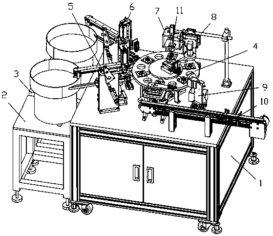
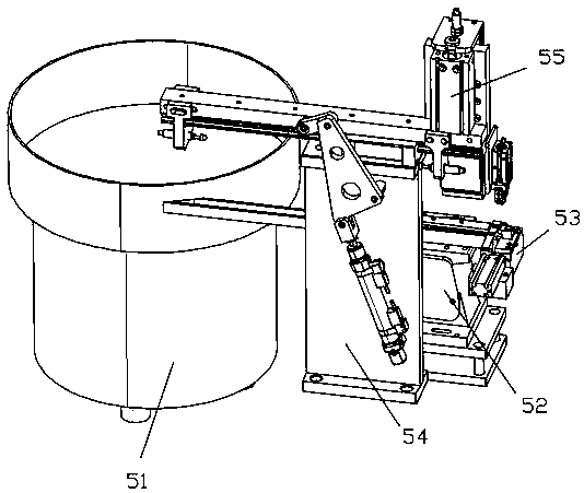
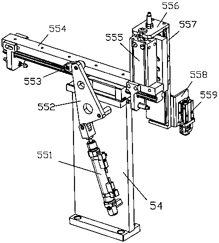
The invention relates to automatic machining equipment for ceramic ferrules. The automatic machining equipment comprises a workbench, wherein a vibrating disk bottom frame I and a vibrating disk bottom frame II are arranged on a left side of the workbench; and the vibrating disk bottom frame I is located on a front side of the vibrating disk bottom frame II. The automatic machining equipment is characterized in that a rotary carrying mechanism is arranged in the middle of an upper surface of the workbench; a sleeve feeding mechanism, a plug feeding mechanism, a press fitting mechanism, a firstappearance detection mechanism I, a second appearance detection mechanism II and a discharging mechanism are sequentially arranged on the periphery of the rotary carrying mechanism in the clockwise rotation direction of the rotary carrying mechanism; a defective product removing mechanism is arranged at an upper end of the rotary carrying mechanism; a material box is fixed to the position, corresponding to a carrying part of the rotary carrying mechanism, on the upper surface of the workbench; the material box is located on a front side of the appearance detection mechanism I; and the sleevefeeding mechanism is used for placing a sleeve on a product positioning seat of the rotary material loading mechanism. The automatic machining equipment is high in automation degree, improves the working efficiency, saves the labor cost, and has good market application value.

Description

technical field [0001] The invention relates to the technical field of powder material packaging equipment, in particular to an automatic processing equipment for ceramic ferrules. Background technique [0002] Fiber optic connector ceramic ferrule, also known as ceramic ferrule body. A precision-centered cylinder in a fiber optic connector plug with a microhole in the center to hold the fiber in place. It is a high-precision special ceramic element made of nano-zirconia (ZrO2) material through a series of formulations and processing. The error of its aperture and true roundness is 0.5 mm. The manufactured connector is a detachable and classified optical fiber active connector, which makes the connection and conversion scheduling of the optical channel more flexible, and can be used for debugging and maintenance of the optical communication system. [0003] At present, the development momentum in the field of optical communication technology is strong. As an important part...

Claims


Application Information

Patent Timeline
IPC IPC(8): G02B6/38
CPCG02B6/3869
Inventor 陆科奇
Owner 深圳市前海中剑辰星科技有限公司
Learn More