
Ultraviolet disinfection device based on optical waveguide, and terminal

An ultraviolet disinfection and optical waveguide technology, applied in disinfection, water supply equipment, sanitary equipment for toilets, etc., can solve the problems of ultraviolet attenuation, increase disinfection time, carcinogenicity, etc., and achieve the effect of less human injury, simple structure, and precise disinfection.

Pending Publication Date: 2020-07-28
王勇竞
View PDF5 Cites 2 Cited by
  • Summary
  • Abstract
  • Description
  • Claims
  • Application Information

AI Technical Summary

Problems solved by technology

[0005] In view of the deficiencies in the above-mentioned prior art, the purpose of the present invention is to provide an ultraviolet disinfection device and terminal based on optical waveguide, which overcomes the serious attenuation of ultraviolet light in the existing ultraviolet disinfection device, which needs to increase the intensity of ultraviolet light and increase the disinfection time ; Long-term exposure of the human body to ultraviolet radiation can cause cancer; the existing disinfection device cannot be integrated on the display device, and it is inconvenient to use and other defects

Method used


Image

  • Ultraviolet disinfection device based on optical waveguide, and terminal
  • Ultraviolet disinfection device based on optical waveguide, and terminal
  • Ultraviolet disinfection device based on optical waveguide, and terminal

Examples


Embodiment 1

[0037] Embodiment 1 of the present invention provides a kind of ultraviolet disinfection device based on optical waveguide, such as Figure 5 As shown, the ultraviolet disinfection device based on optical waveguide includes a first ultraviolet light source, a first optical coupler 502 and a first optical waveguide optical film 503, and the first optical waveguide optical film 503 includes a first base layer 5031 and the first flat light guide film layer 5032 . The structure of the ultraviolet disinfection device in this embodiment is the same as that of the ultraviolet disinfection device mentioned in the preceding steps, the only difference is that the first optical coupler 502 in this embodiment is a grating coupler, and the first optical coupler 502 is a grating coupler. The coupler 502 is a periodic grating structure disposed on the first flat light guide film layer 5032 . After the incident light enters the first optical waveguide light-guiding film 503 through the first...

Embodiment 2

[0039] Embodiment 2 of the present invention provides a kind of ultraviolet disinfection device based on optical waveguide, such as Image 6 As shown, the ultraviolet disinfection device based on optical waveguide includes a second ultraviolet light source, a second optical coupler 602 and a second optical waveguide light guiding film 603, and the second optical waveguide light guiding film 603 includes a second base layer 6031 And the second flat light guide film layer 6032. The structure of the ultraviolet disinfection device described in this embodiment is the same as the structure of the ultraviolet disinfection device mentioned in the preceding steps, the only difference is that the second optical coupler 602 described in this embodiment is a prism coupler, when incident to the second When the incident angle of the ultraviolet light at the bottom of the optical coupler 602 is greater than the critical angle of total reflection, an evanescent field will be generated in the...

Embodiment 3

[0041] Embodiment 3 of the present invention provides a kind of ultraviolet disinfection device based on optical waveguide, such as Figure 7 As shown, the ultraviolet disinfection device based on optical waveguide includes a third ultraviolet light source, a third optical coupler 702 and a third optical waveguide light guiding film 703 ', and the third optical waveguide light guiding film 703 includes a third base layer 7031 and the third flat light guide film layer 7032. The structure of the ultraviolet disinfection device described in this embodiment is the same as that of the ultraviolet disinfection device mentioned in the preceding steps, the only difference is that the third optical coupler 702 described in this embodiment is a lens coupler, and the third optical coupler 702 is used to couple The device 702 focuses the ultraviolet light provided by the ultraviolet light source directly on the end surface of the third flat light-guiding film layer 7032, and the ultraviol...


PUM


Abstract

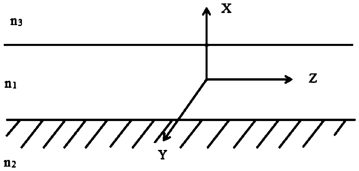
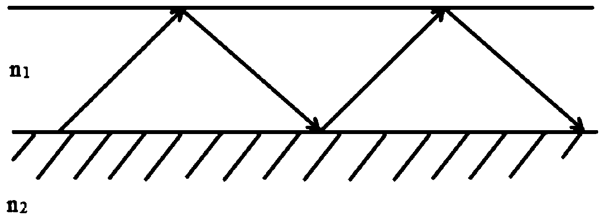
The invention provides an ultraviolet disinfection device based on optical waveguide, and a terminal. The ultraviolet disinfection device comprises an ultraviolet light source, an optical coupler andan optical waveguide light-guiding thin film, wherein the optical waveguide light-guiding thin film comprises a basal layer and a flat-slab light-guiding thin film from bottom to top; the refractive index of the basal layer is smaller than the refractive index of the flat-slab light-guiding thin film; the ultraviolet light source is used for providing ultraviolet light used for disinfection; the optical coupler is used for receiving the ultraviolet light and coupling and importing the ultraviolet light into the optical waveguide light-guiding thin film; and the optical waveguide light-guidingthin film is transparent for the ultraviolet light and is used for receiving the ultraviolet light to disinfect the surface of the optical waveguide light-guiding thin film. Through the optical waveguide light-guiding thin film, the ultraviolet light imported from the optical coupler is received, the ultraviolet light generates total reflection in the optical waveguide light-guiding thin film anddoes not generate attenuation along with distance, and the ultraviolet light only generates light leakage on a dirt adhesion position so as to generate small injuries on the human body. The device issimple, can be integrated to display equipment to carry out ultraviolet disinfection on the display equipment if required, and is convenient to use.

Description

technical field [0001] The invention belongs to the technical field of ultraviolet disinfection devices, and in particular relates to an optical waveguide-based ultraviolet disinfection device and a terminal. Background technique [0002] Human beings have been plagued by various diseases for a long time, and many diseases are caused by human contact with bacteria or viruses through hands. Washing your hands frequently and properly is crucial to reducing the spread of disease, but it can make our lives safer if we can eliminate viruses at their source - the many surfaces that our hands touch every day. Various buttons, handles, keyboards, mobile phone screens and other objects that cannot be avoided in our daily life are often the main source of various bacteria and viruses, especially mobile phone screens. Studies have shown that the amount of bacteria on mobile phone screens is higher than that of randomly collected ATMs. There are many keyboards, toilet flush buttons, an...

Claims


Application Information

Patent Timeline
IPC IPC(8): A61L2/10A61L2/26A61L2/24
CPCA61L2/10A61L2/26A61L2/24A61L2202/11A61L2202/14
Inventor 王昊承郑港张喜玉王勇竞杨全平王举芳刘国成
Owner 王勇竞
Learn More