
Barrel punch forming device

A stamping and forming, cylinder technology, applied in stamping machines, forming tools, presses, etc., can solve the problems of poor stamping resistance, easy cracking and bonding of aluminum alloys

Pending Publication Date: 2020-07-28
长春森酉科技有限公司
View PDF0 Cites 0 Cited by
  • Summary
  • Abstract
  • Description
  • Claims
  • Application Information

AI Technical Summary

Problems solved by technology

[0003] With the rapid development of the automobile industry, the problems of environmental pollution and resource shortage have become increasingly prominent. Saving resources and reducing pollution have become two major issues to be solved in the automobile industry. Focusing on sustainable development, reduce the quality of automobiles, reduce fuel consumption and reduce emission pollution The task is particularly urgent, automobile lightweight technology is one of the important ways to solve these problems, research results show that every 10% reduction in automobile mass can reduce fuel consumption by 6-8%; although aluminum alloy has the advantage of light weight, in It is widely used in body structure, but the aluminum alloy is not good at stamping pressure, and it is easy to break during the stamping process. If the stamping force is reduced during the stamping process, it is easy to bond with the stamping.
[0004] The current stamping machinery and equipment are generally large-scale stamping machines. The stamping machine is fixed in the workshop. When working, the workpieces such as plates or wires are placed on the workbench. A huge stamping block on the upper part of the stamping machine moves through hydraulic pressure or free fall. Stamping the plate or wire, and bending the stamped plate and wire into various desired shapes, it is difficult to stamp the already bent cylindrical structure

Method used


Image

  • Barrel punch forming device
  • Barrel punch forming device
  • Barrel punch forming device

Examples


Embodiment Construction

[0024] The core of the present invention is to provide a cylinder stamping and forming device capable of stamping and processing a cylinder structure.

[0025] In order to enable those skilled in the art to better understand the technical solution of the present invention, the cylinder stamping and forming device of the present invention will be described in detail below with reference to the drawings and specific embodiments.

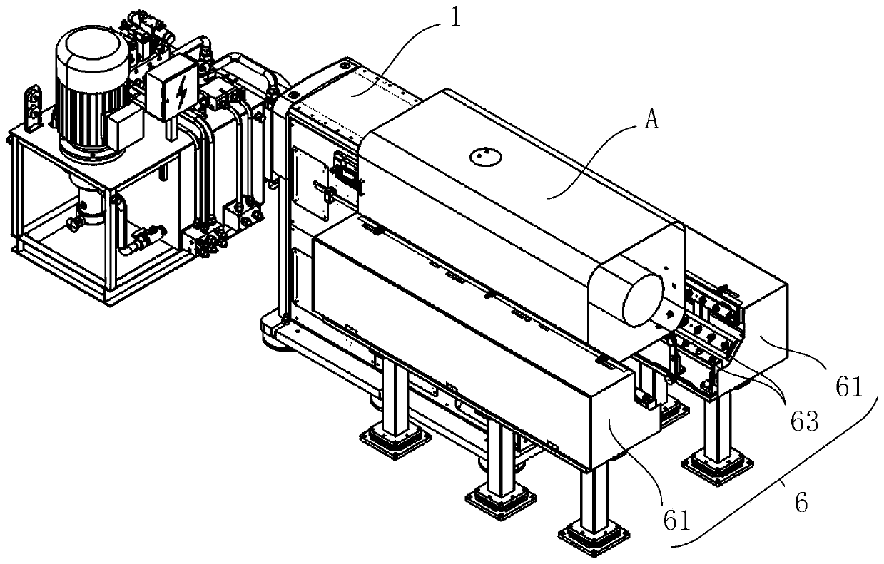
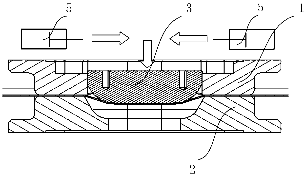
[0026] Such as figure 1 Shown is a schematic diagram of the structure of the cylinder stamping and forming device provided by the present invention, where A represents the cylinder to be processed. The device includes an upper mold 1 that can extend into the cylinder and a lower mold 2 located outside the cylinder, such as Figure 2A Shown is a structural diagram of the relative device of the upper mold 1, the lower mold 2 and the punch 3, the upper mold 1 and the lower mold 2 cooperate with each other to clamp the surface of the cylinder to be punched; the u...


PUM


Abstract

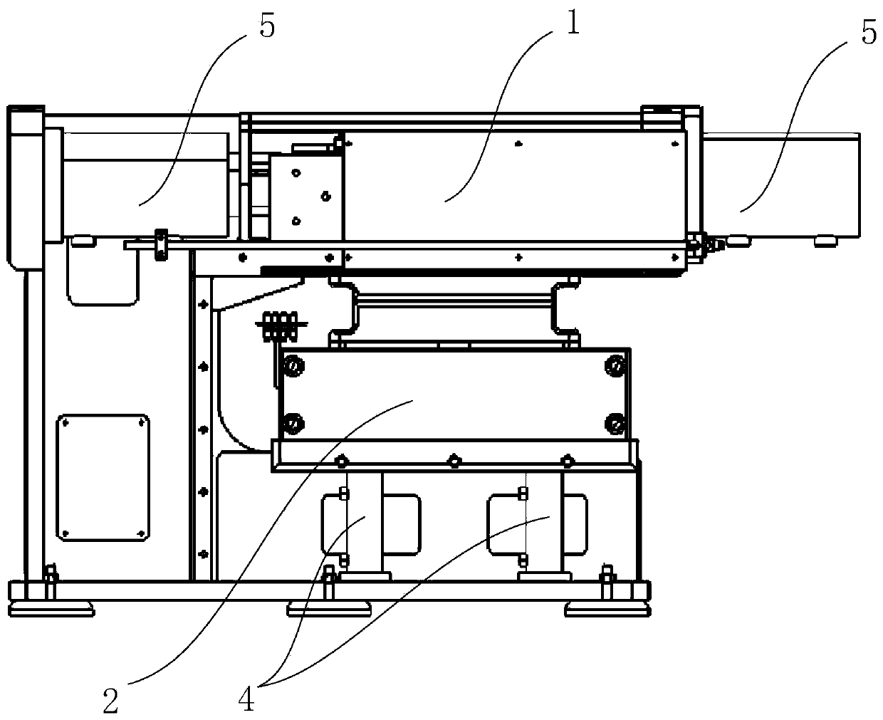
The invention discloses a barrel punch forming device which comprises an upper die capable of extending into a barrel and a lower die located outside the barrel. The upper die and the lower die are matched with each other to clamp the barrel, a male die is movably arranged on the upper die, a groove for avoiding is formed in the lower die, and the male die can conduct punching on the surface of the barrel; the upper die is a cantilever and is fixedly arranged, and the upper die is kept fixed in the operation process; the lower die is driven by a clamping driver and can move to be close to or away from the upper die so as to clamp or loosen the barrel; the male die is driven by a punching driver to punch, and an avoiding space is provided by the groove in the lower die; the moving directionof the punching driver is perpendicular to the moving direction of the male die, so that the punching driver can be placed in a cavity in the barrel to punch the barrel; and the barrel punch formingdevice can punch a machined and formed barrel structure.

Description

Technical field [0001] The invention relates to the technical field of stamping equipment, and further relates to a cylinder stamping forming device. Background technique [0002] In recent years, high-speed and efficient production of stamping parts has become an important indicator for stamping companies to occupy the market. In automobile manufacturing, 60%-70% of metal parts need to be formed by plastic processing. Stamping is an important means to complete metal plastic forming. One of the most basic, traditional and important metal processing methods. [0003] With the rapid development of the automobile industry, the problems of environmental pollution and resource shortage are becoming more and more prominent. Saving resources and reducing pollution have become the two major problems to be solved in the automobile industry. Focusing on sustainable development, reducing automobile quality, reducing fuel consumption and reducing emissions pollution The task of automobile lig...

Claims


Application Information

Patent Timeline
IPC IPC(8): B21D22/02B21D37/10B21C51/00B30B15/26B21D53/88
CPCB21C51/00B21D22/02B21D37/10B21D53/88B30B15/26B30B1/40
Inventor 车柏乐黄春梅毕海涛于征复秦朝阳
Owner 长春森酉科技有限公司
Learn More