Riveting equipment and method for home appliance panel

A riveting and panel technology, applied in metal processing equipment, storage devices, feeding devices, etc., can solve the problems of weak solder joints, unfavorable fast and accurate positioning, and low connection strength, so as to improve reliability and connection strength, avoid Solder joints are weak and the effect of improving riveting efficiency

Active Publication Date: 2021-12-14
顾鑫
View PDF5 Cites 0 Cited by
  • Summary
  • Abstract
  • Description
  • Claims
  • Application Information

AI Technical Summary

Problems solved by technology

[0005] The purpose of the present invention is to solve the problems of poor reliability and low connection strength due to the weak spot welding spot welding of connecting plates in the prior art; rivet connection needs to pre-process hole positions, which is time-consuming and laborious, which is not conducive to the maintenance of home appliance panels. Fast and efficient processing; manual positioning or frequent replacement of mold positioning each time is not conducive to fast and accurate positioning. A method of stamping and riveting the home appliance panel through a pressurized cylinder is proposed to make the surface of the home appliance panel plastically deformed, and the structure is finer. It solves the problem of weak solder joints, high reliability and high connection strength; four riveting mechanisms work at the same time, no need to pre-process holes, and efficient riveting; variable pitch cylinder positioning, no need to change molds frequently, can complete positioning quickly and accurately Riveting equipment and method for home appliance panel

Method used


Image

  • Riveting equipment and method for home appliance panel
  • Riveting equipment and method for home appliance panel
  • Riveting equipment and method for home appliance panel

Examples


Embodiment 1

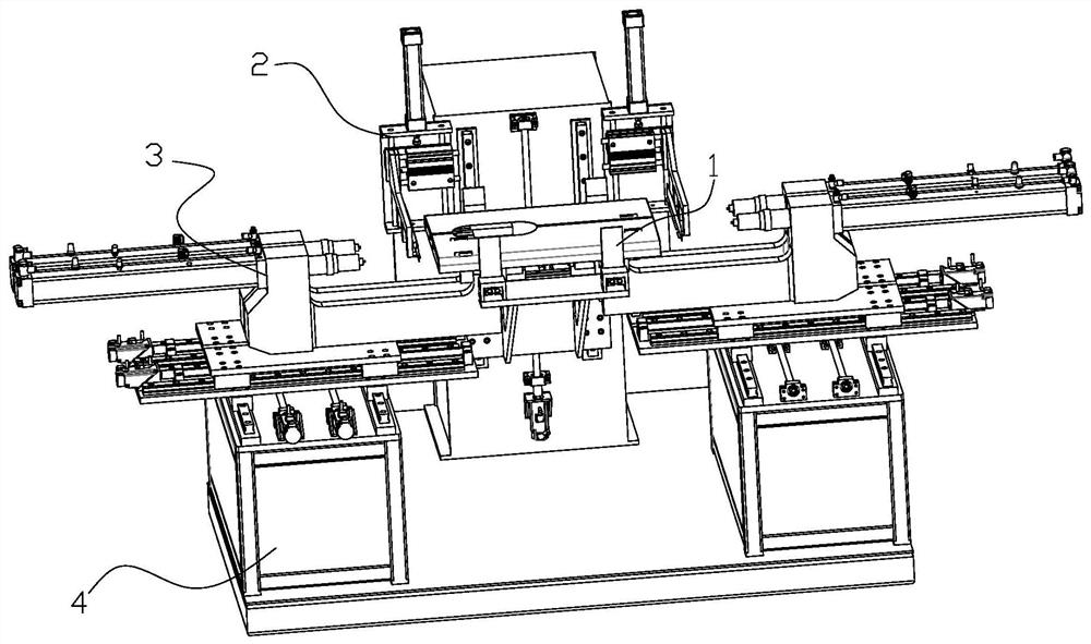
[0040] like figure 1 Shown is a home appliance panel riveting device, which includes a bottom plate positioning mechanism 1 , a side plate positioning mechanism 2 , a riveting mechanism 3 and a frame 4 . The base plate positioning mechanism 1 , the side plate positioning mechanism 2 and the riveting mechanism 3 are all fixed on the frame 4 . The two riveting mechanisms 3 are fixed to the upper end surface of the frame 4 and are located on the left and right sides of the frame 4 respectively. The bottom plate positioning mechanism 1 is fixed on the front end surface of the middle column of the rack 4 , and the two side plate positioning mechanisms 2 are fixed above the bottom plate positioning mechanism 1 and are located on the left and right sides of the bottom plate positioning mechanism 1 respectively.

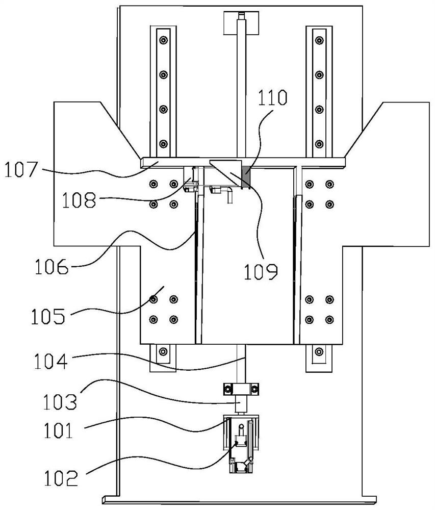
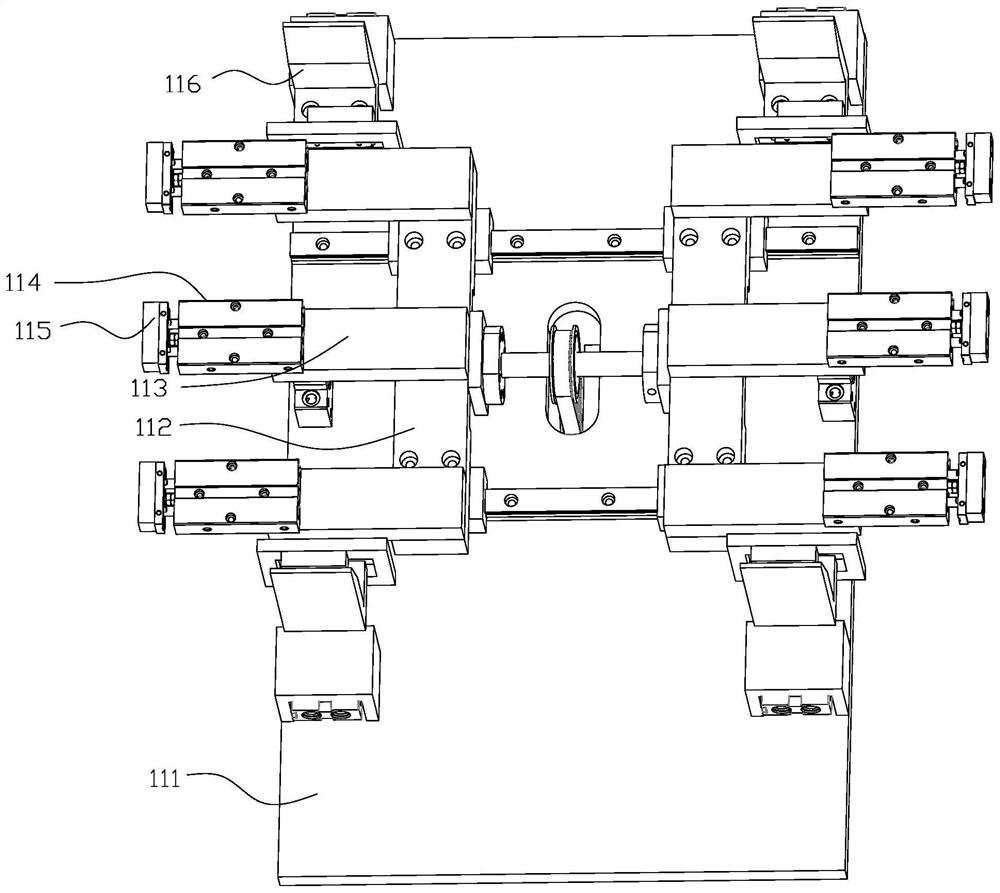
[0041] like figure 2 image 3 As shown, the baseplate positioning mechanism 1 includes a baseplate first drive motor 101, a baseplate first drive motor seat 102, a coupl...


PUM


Abstract

The invention relates to the field of household appliance panel riveting, in particular to a household appliance panel riveting device and method. The equipment includes a bottom plate positioning mechanism, a side plate positioning mechanism, a riveting mechanism and a frame. The bottom plate positioning mechanism, the side plate positioning mechanism and the riveting mechanism are all fixed on the frame, and the two riveting mechanisms are fixed on the end surface of the bottom surface of the frame, and are respectively located on the left and right sides of the frame, and the bottom plate positioning mechanism is fixed in the middle of the frame On the front end of the column, two side plate positioning mechanisms are fixed above the bottom plate positioning mechanism, and are respectively located on the left and right sides of the bottom plate positioning mechanism. The device can quickly complete the connection work of the home appliance panel, improve the efficiency and quality of the home appliance panel connection, and simultaneously reduce the production cost of the home appliance panel connection.

Description

technical field [0001] The invention relates to the field of home appliance panel riveting, in particular to a home appliance panel riveting device and method. Background technique [0002] With the development of science and technology, the riveting process of home appliance panels is more and more widely used in factories. At present, there are many ways to connect home appliance panels, and various panel connection equipment is also more and more important. status. With the rapid development of home appliance panel connection equipment, more and more attention has been paid to the accuracy requirements of home appliance panel connection and processing, the connection quality after home appliance panel connection and the efficiency of home appliance panel connection processing. The overall processing quality and processing efficiency of the home appliance panel have an important impact. [0003] When connecting the general home appliance panels, there are usually two met...

Claims


Application Information

Patent Timeline
Patent Type & Authority Patents(China)
IPC IPC(8): B21D39/00B21D43/00
CPCB21D39/00B21D43/003
Inventor 王加县曹春云曹二菊
Owner 顾鑫
Why Eureka
Try Eureka