Steel wire rope cutting-off, clamping, correcting and tensioning combined device and using method

A technology of combining device and steel wire rope, applied in the field of steel wire rope, can solve the problems of complex structure, single function of the device, not suitable for automatic production line, etc., and achieve the effect of good structural combination.

Active Publication Date: 2020-07-28
SHANDONG JIAOTONG UNIV
View PDF9 Cites 3 Cited by
  • Summary
  • Abstract
  • Description
  • Claims
  • Application Information

AI Technical Summary

Problems solved by technology

[0004] In order to solve the problems that most of the devices in the prior art related to the functions of cutting, clamping, straightening, and tensioning stainless steel wire ropes have single functions, complex structures, and are not suitable for automatic production lines, etc., the present invention provides a cutting, clamping, etc. , straightening, tensioning stainless steel wire rope and other multi-functional combination devices, and provide its use method

Method used


Image

  • Steel wire rope cutting-off, clamping, correcting and tensioning combined device and using method
  • Steel wire rope cutting-off, clamping, correcting and tensioning combined device and using method
  • Steel wire rope cutting-off, clamping, correcting and tensioning combined device and using method

Examples


Embodiment 1

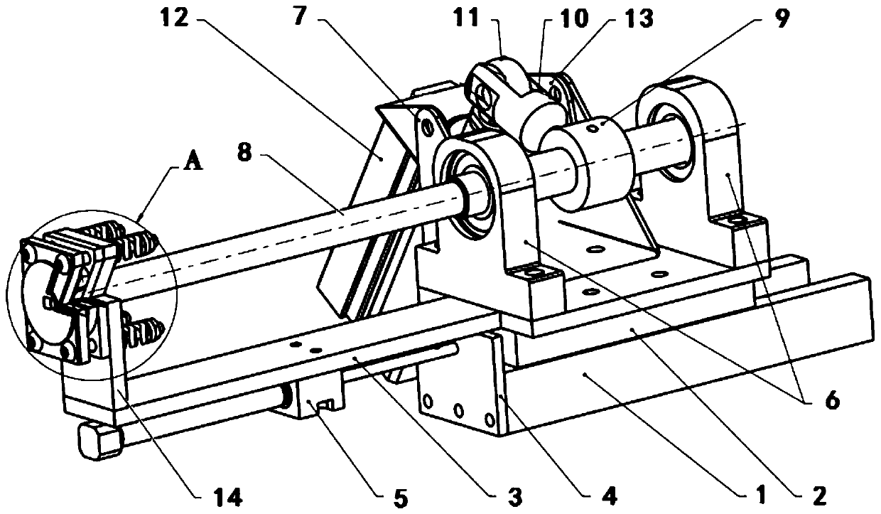
[0052] In Embodiment 1, a device structure capable of fully realizing all functions of cutting, clamping, straightening, and tensioning is provided.

[0053] Such as figure 1 As shown, the device includes a guide rail 1 fixedly installed on the substrate, a guide rail slide 2 is installed on the guide rail 1, the guide rail slide 2 can slide linearly on the guide rail 1, and a relatively long guide rail slide 2 is fixedly installed on the top Mounting plate 3; a piston rod mounting plate 4 is fixed at one end of the guide rail 1, the piston rod of the No. 1 cylinder 5 is fixed on the piston rod mounting plate 4, and the cylinder body of the No. 1 cylinder 5 is fixed at the bottom of the mounting plate 3. When the cylinder 5 is working , due to the reaction of the force, the piston rod does not move, and the cylinder moves, which in turn drives the mounting plate 3 and the guide rail slide table 2 to slide. The advantages of this design are: one, the fixed support parts of the...

Embodiment 2

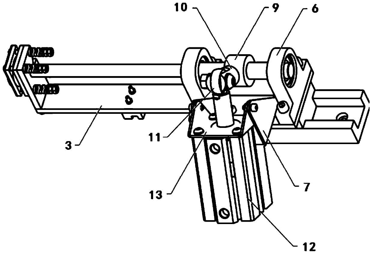
[0087] In embodiment 2, a device structure for realizing cutting, clamping and tensioning is provided, such as Figure 7 shown.

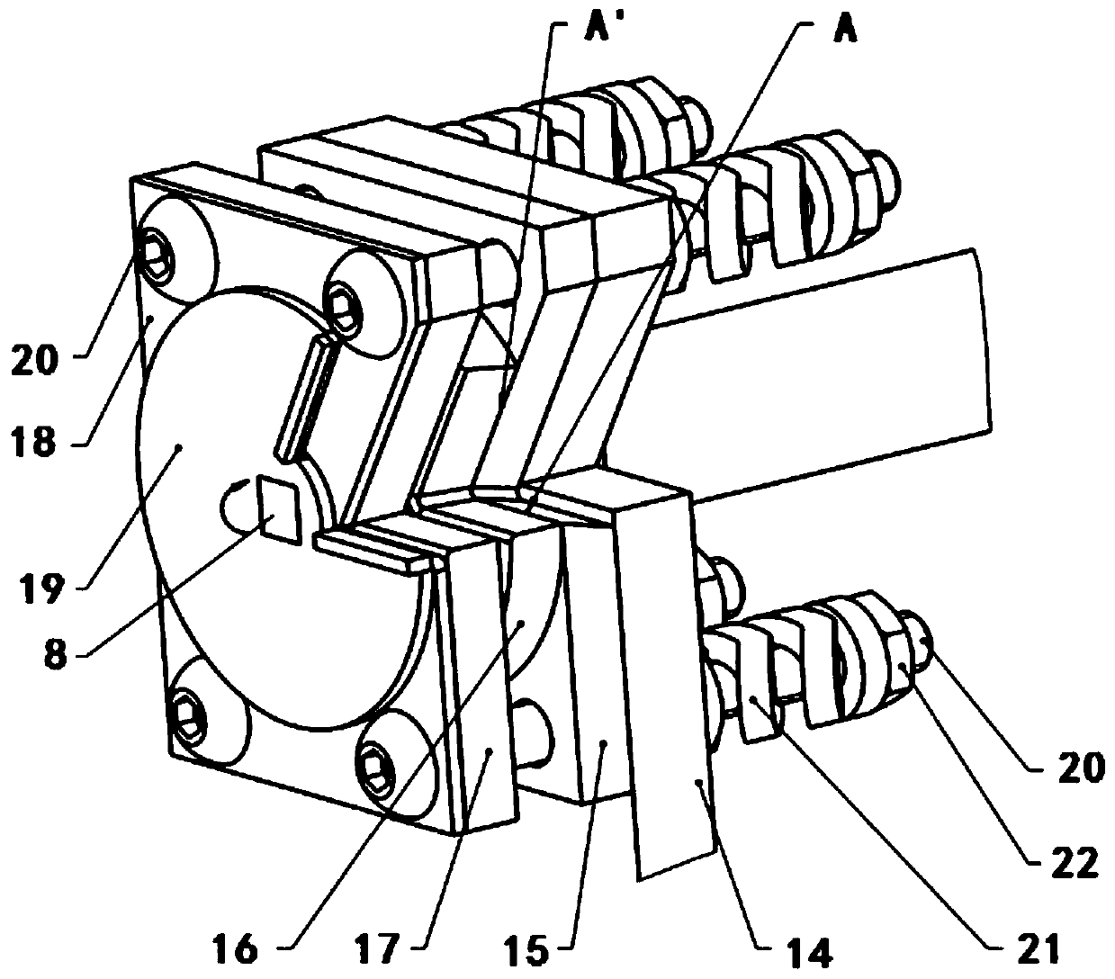
[0088] The difference between embodiment 2 and embodiment 1 is that the correction plate 1 18 and correction plate 2 19 are removed, and the shaft end of the rotating shaft in the cutting and clamping assembly is installed to cut and clamp the supporting plate 14, cut off the clamping plate 15, cut off the clamping plate 16, Clamping plate 17 , bolt 20 , spring 21 and nut 22 .

[0089] Refer to Example 1 for the method of use. The cutting and clamping support plate 14 is installed with a plurality of bolts to cut off the cutting plate 15, the cutting and clamping plate 16, the clamping plate 17, the spring 21 and the nut 22, which do not move with the rotating shaft; the spring 21 is used to adjust the cutting The clamping between the plate 15 and the clamping plate 17 cuts off the pre-tightening force of the clamping plate 16; the rotation of the ...

Embodiment 3

[0091] In Embodiment 3, a device structure that only realizes cutting and clamping is provided.

[0092] The difference between embodiment 3 and embodiment 1 is that the guide rail 1, the guide rail slide table 2, and the No. 1 cylinder 5 are removed, the mounting plate 3 and the clamping support plate 14 are kept, and the bearing assembly and the No. 2 cylinder assembly are directly installed on the mounting plate 3. On, cut off and clamp support plate 14, cut off plate 15, cut off clamping plate 16, clamping plate 17 are installed in the shaft end of rotating shaft in the clamping assembly, and are locked by bolt 20, spring 21 and nut 22.

[0093] in working:

[0094] 1. First, use the No. 2 cylinder device 12 to drive the rotation shaft 8 to rotate through the fish-eye connector 11, the connecting rod 10, and the fixing ring 9, and drive the rotation of the cutting clamping plate 16 to make the gap of the cutting clamping plate 16 and the cutting clamping support Plate 14,...


PUM


Abstract

The invention discloses a steel wire rope cutting-off, clamping, correcting and tensioning combined device and a using method. According to the combined device and the using method, a steel wire ropeis placed in a device notch, along with rotation of a rotating shaft, the steel wire rope is cut off through a cutting-off clamping plate, rotation is continued, the steel wire rope is clamped betweena clamping plate and the cutting-off clamping plate through the cutting-off clamping plate, then the rotation is continued, a correcting plate corrects the stainless steel wire rope, and a mounting plate moving assembly moves for a certain distance to tension the steel wire rope. And therefore, cutting-off, clamping, correcting and tensioning type automatic production of the steel wire rope in the weaving process is achieved.

Description

technical field [0001] The invention relates to the field of steel wire ropes, in particular to a multifunctional device and method for cutting, clamping, straightening, and tensioning stainless steel wire ropes. Background technique [0002] Common steel wire ropes include carbon steel wire ropes and stainless steel wire ropes. Stainless steel wire rope has many advantages such as good high temperature resistance, good fatigue resistance, excellent breaking force, long service life, durable, beautiful and anti-corrosion, etc. It is widely used in coal, petroleum, metallurgy, chemical industry, shipbuilding, bridges, electricity, rubber, Military industry, tourism, water conservancy, light industry and other industries. [0003] However, in the process of using steel wire ropes to weave nets, and because of their strong tensile and breaking capabilities, most of the devices involving functions such as cutting, clamping, straightening, and tensioning of stainless steel wire ...

Claims


Application Information

Patent Timeline
IPC IPC(8): B21F27/02B21F11/00B21F1/00B21F1/02
CPCB21F1/004B21F1/026B21F11/00B21F27/02
Inventor 刘均海宋桂香付振山丁进
Owner SHANDONG JIAOTONG UNIV
Why Eureka
Try Eureka