Metal hose connector shielded welding device

A metal hose and shielded welding technology, applied in metal processing equipment, welding equipment, welding accessories, etc., can solve problems such as inability to solve reliable in-situ welding, and achieve the effect of avoiding poor positioning accuracy and ensuring consistency

Pending Publication Date: 2020-07-28
AEROSUN CORP
View PDF5 Cites 2 Cited by
  • Summary
  • Abstract
  • Description
  • Claims
  • Application Information

AI Technical Summary

Problems solved by technology

However, none of the above-mentioned prior art is designed for gas-shielded welding of small-diameter metal hose joints, so it cannot solve the problems of reliable in-situ welding of the end of the metal bellows and the joint assembly in a gas-shielded environment, and easy removal after welding.

Method used


Image

  • Metal hose connector shielded welding device
  • Metal hose connector shielded welding device
  • Metal hose connector shielded welding device

Examples


Embodiment 1

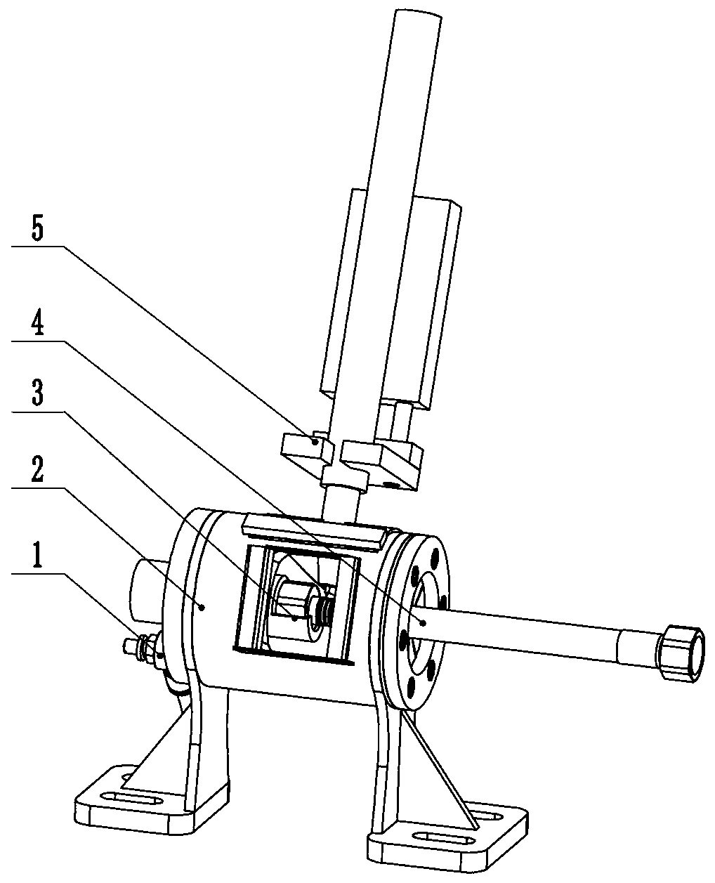
[0034] This embodiment is a protective welding device for metal hose joints used in cookers, and its basic structure is as follows: figure 1 As shown, it includes a ventilation interface 1, a closed cavity unit 2, a joint assembly positioning unit 3, a welding torch telescopic positioning unit 5, and a metal bellows unit 4 is placed in the joint assembly positioning unit 3 for welding positioning.

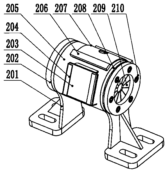
[0035] combine figure 2 It can be seen that the cylindrical hollow airtight chamber 205 as the main body of the airtight chamber unit 2 is supported on the vertical brackets 201 at its two ends, the front side has a welding observation port 204 for inserting the arc filter eyepiece 203, and the upper part is supported by a powerful magnetic block 206 The welding torch gasket 207 is fixed, and the middle part of the welding torch gasket 207 has a welding torch insertion hole. The two ends of the airtight chamber 205 are respectively equipped with a positioning end cap 202 and an ...

Embodiment 2

[0043] The basic structure of the shielded welding device for metal hose joints used in cooktops in this embodiment is the same as that of the embodiment, except that the metal hoses to be welded are such as Figure 10 As shown, it is a metal bellows with a socket threaded connection structure, which includes a socket threaded joint assembly 405, a bellows 403, a buckle ring 402, and a PVC coating 404. The socket thread assembly 405 is composed of a socket thread 4052 and a welded joint 4051. The corrugated pipe 403 is covered with a layer of PVC coating 404 and 2-3 corrugations are reserved at both ends. Before the two ends are welded, the crimping ring 402 is inserted. For this reason, its joint assembly positioning unit 3 such as Figure 11 and Figure 12 As shown, it includes a guide core rod 303, a lock nut 301, and a socket-type positioning slider 304, so the slider body of the positioning slider 304 is slightly different from that of the first embodiment.

[0044] Pra...


PUM


Abstract

The invention relates to a metal hose connector shielded welding device and belongs to the technical field of welding devices. The upper part of an airtight cavity unit of the device is provided witha welding gun insertion hole and provided with a welding gun extending and retracting locating unit. The two ends of the airtight cavity unit are provided with a locating end cover and an insertion end cover correspondingly. The locating end cover fixes a guide core rod. The outer circle of the guide core rod is matched with the inner diameter of a metal corrugated pipe. A locating slide block isinstalled on the guide core rod. The outer section of the locating slide block is provided with a centering recession. A flap rubber seal mat is installed in an insertion hole of the insertion end cover and is composed of a group of rubber sheets, wherein the outer end of each rubber sheet is fixed, and the inner ends of the rubber sheets are elastically closed. The metal hose connector shielded welding device well solves the gas shielded welding problem of the metal hose for a kitchen range pipe. The metal hose connector shielded welding device can efficiently complete rapid welding of metalhoses in batches, avoids the defects that by the adoption of manual locating, precision is poor, and welded portions are not flat, and guarantees the welding quality consistency.

Description

technical field [0001] The invention relates to a small-caliber metal hose welding device, in particular to a metal hose joint protection welding device, which belongs to the technical field of welding equipment. Background technique [0002] Small-diameter metal hoses, such as metal hoses for stoves, require comprehensive properties such as flexibility, vibration resistance, pressure resistance, corrosion resistance, and fatigue resistance. components. Its commonly used joint components have G1 / 2 thread and socket thread structure (see Figure 7 , Figure 10 )Wait. During manufacture, after the metal bellows is covered with a layer of PVC protective layer, the end of the bellows is subjected to half-wave knocking (that is, flattening) treatment, and then the crimping ring is put on, and then it is butt ring-welded with the joint assembly. [0003] For a long time, the small-diameter metal hoses used in stoves have been welded openly with the traditional simple welding po...

Claims


Application Information

Patent Timeline
IPC IPC(8): B23K9/16B23K9/32
CPCB23K9/16B23K9/32
Inventor 刘永叶朝晖朱广松
Owner AEROSUN CORP
Why Eureka
Try Eureka