Supercharge Your Innovation With Domain-Expert AI Agents!

Material distributing mechanism of material conveying system

A technology of conveying system and material distribution mechanism, which is applied in the direction of conveyor objects, transportation and packaging, loading/unloading, etc., and can solve problems such as the failure to realize the material distribution function normally, the loss of adjustment function of the adjustment screw, and the position deviation of the material guide. , to achieve high internal space utilization, strong reliability and practicability, and avoid collisions

Pending Publication Date: 2020-07-28
HUADIAN HEAVY IND CO LTD
View PDF0 Cites 0 Cited by
  • Summary
  • Abstract
  • Description
  • Claims
  • Application Information

AI Technical Summary

Problems solved by technology

[0005] Its adjusting screw is connected with the shield. When the material impacts on the material guide, the impact force on the material guide acts on the shield through the adjustment screw. The long-term high-strength impact of the material on the material guide will cause the adjustment screw Bending will eventually lead to the deformation of the adjusting screw, the adjusting screw will lose its adjustment function, and will cause the position of the material guide to deviate, resulting in the failure to realize the normal material distribution function, and the aperture of the installation hole where the adjusting screw is installed on the shield will also change. Large, resulting in dust leakage

Method used


Image

  • Material distributing mechanism of material conveying system
  • Material distributing mechanism of material conveying system
  • Material distributing mechanism of material conveying system

Examples


Embodiment 1

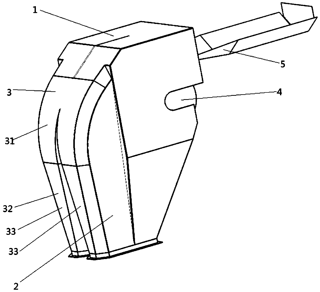
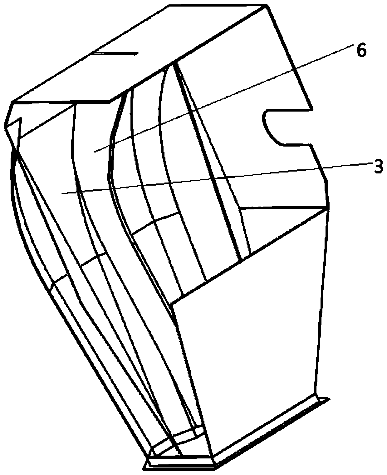
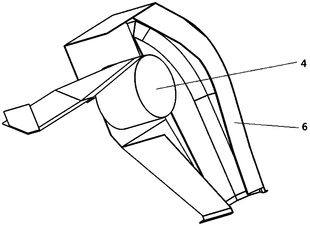
[0040] This embodiment provides a specific implementation of the material distribution mechanism of the material delivery system, such as Figure 1 to Figure 3 As shown, the material distributing mechanism includes a housing and a partition plate 6 .

[0041]One side wall of the housing is a material guide structure 3, which is used to guide the material to flow along a preset direction; the partition plate 6 is arranged on the material guide structure 3 and is located in the housing, and the partition plate 6 is provided with At least one for dividing material into strands. Specifically, the partition plate is vertically arranged on the material guide structure 3. Since one side wall of the housing is the material guide structure 3, the overall strength is relatively high, and the position of the material guide structure 3 will not change after being impacted by the material. , and then the position of the partition plate 6 arranged on the material guide structure 3 will not...


PUM


Abstract

The invention relates to the technical field of material conveying, in particular to a material distributing mechanism of a material conveying system. The material distributing mechanism comprises a shell and a partition plate, wherein one side wall of the shell is provided with a material guide structure, and the material guide structure is used for guiding materials to flow along a preset direction; and the partition plate is arranged on the material guide structure and located in the shell, and at least one partition plate is arranged and used for dividing the materials into a plurality ofstrands. Due to the fact that one side wall of the shell is provided with the material guide structure, the overall strength is high, after the material guide structure is subjected to the impact force of the materials, the position of the material guide structure cannot be changed, and then the position of the partition plate arranged on the material guide structure cannot be changed so that thematerial distributing function can be guaranteed; and the material distributing mechanism is good in material impact resistance, simple in structure and high in reliability and practicability, the shell is good in sealing performance, dust can be prevented from leaking outwards, and no redundant structure is arranged inside the shell, so that the internal space utilization rate is high, and the anti-blocking effect is good.

Description

technical field [0001] The invention relates to the technical field of material conveying, in particular to a material distributing mechanism of a material conveying system. Background technique [0002] In the material conveying system, the material distribution mechanism is used to move the material on the conveyor belt to the next station. Most of the existing material distribution mechanisms have the material distribution function, and the material distribution mechanism with the material distribution function can transport the materials to different branch roads respectively. The material distribution mechanism with material distribution function plays an important role in the process of connecting different process equipment and distributing materials. [0003] The material distributing mechanism in the prior art is commonly the turnover plate type material distribution mechanism, which includes a turnover plate that is turned around the rotation axis. When it is blo...

Claims


Application Information

Patent Timeline
IPC IPC(8): B65G47/24B65G11/02B65G11/20B65G69/18
CPCB65G11/026B65G11/206B65G47/24B65G69/181
Inventor 刘晓朋张战胜赵勇毕婷婷付衡业
Owner HUADIAN HEAVY IND CO LTD
Features
  • R&D
  • Intellectual Property
  • Life Sciences
  • Materials
  • Tech Scout
  • Unparalleled Data Quality
  • Higher Quality Content
  • 60% Fewer Hallucinations
Learn More