Supercharge Your Innovation With Domain-Expert AI Agents!

Oil separator

A technology for separators and petroleum, applied in the direction of isolation devices, production fluids, wellbore/well components, etc., can solve the problems of weakened flow of oil inlet pipes, reduced gas separation effect, increased viscosity of heavy oil, etc., to reduce the precipitation of wax crystallization, increasing temperature, and improving fluidity

Active Publication Date: 2020-07-28
山东禧龙石油装备有限公司
View PDF6 Cites 3 Cited by
  • Summary
  • Abstract
  • Description
  • Claims
  • Application Information

AI Technical Summary

Problems solved by technology

[0002] The sediment (wax cake) produced in the production process of the oil well is usually solid or semi-solid, and the main component is paraffin. The sediment makes the crude oil have a high viscosity. Separation of oil, gas and water, but because the heavy oil contains more paraffin, the temperature of the oil flow from the bottom of the well to the wellhead during the production of the oil well gradually decreases, and the paraffin forms wax crystals, which are continuously precipitated, causing the heavy oil to solidify , to increase the viscosity of the heavy oil. When the heavy oil enters the oil separator, the circulation of the oil inlet pipe on the oil separator is weakened, and the oil inlet pipe is prone to reverse flow, and the heavy oil is easy to adhere to the inner wall of the oil separator, resulting in thick Air bubbles form in the upper layer of the oil, reducing the separation effect of the gas

Method used


Image

  • Oil separator
  • Oil separator
  • Oil separator

Examples


Embodiment 1

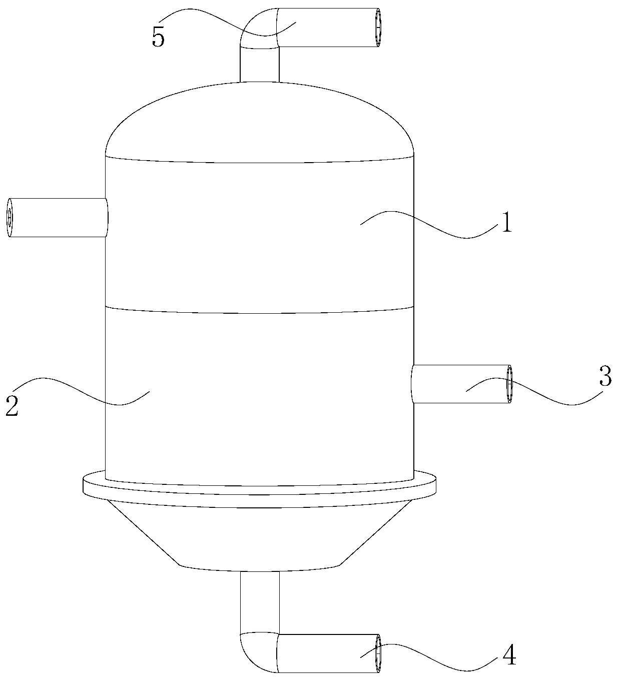
[0024] as attached figure 1 to attach Figure 5 Shown:

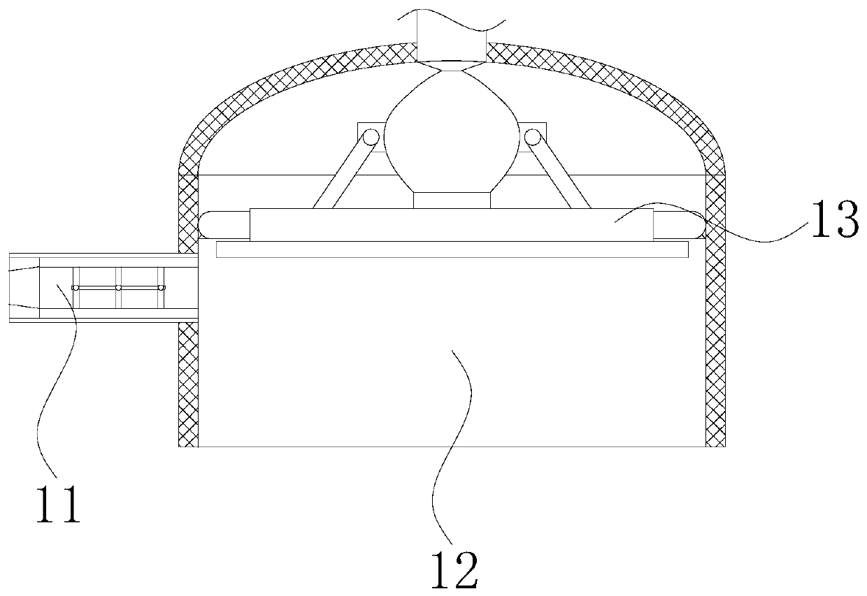
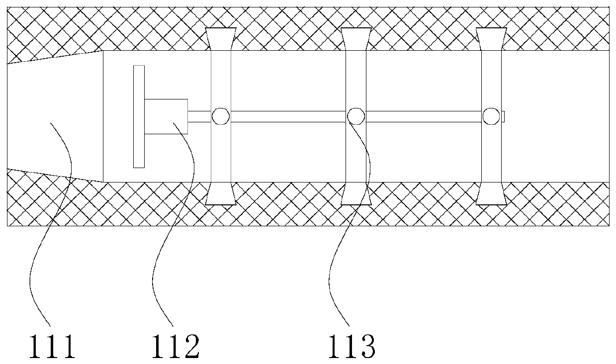
[0025] The present invention is a kind of petroleum separator, its structure comprises inlet tank 1, separation tank 2, oil outlet pipe 3, water outlet pipe 4, gas outlet pipe 5, and described inlet tank 1 is fixedly installed on the upper end of separation tank 2 and interpenetrates, and described separating The right side of the tank 2 is embedded with an oil outlet pipe 3 and communicates with each other. The bottom of the separation tank 2 is fixed with a water outlet pipe 4. The top of the inlet tank 1 is embedded with an air outlet pipe 5 and communicates with each other. The inlet tank 1 includes an oil inlet pipe 11 , tank body 12, airbag mechanism 13, the oil inlet pipe 11 is embedded in the left side of the tank body 12 and communicates with each other, the inner upper end of the tank body 12 is equipped with an airbag mechanism 13, and the upper end of the airbag mechanism 13 communicates with the air outlet ...

Embodiment 2

[0032] as attached Figure 6 to attach Figure 8 Shown:

[0033] Wherein, the air bag mechanism 13 includes an air inlet 131, an air bag 132, a push rod 133, and a scraper 134. The air inlet 131 is fixedly installed on the bottom of the air bag 132 and communicates with each other. The upper end of the air bag 132 is connected to the outlet pipe 5. Through, the airbag 132 is provided with push rods 133 on the left and right sides, the lower end of the push rod 133 is fixed to the inside of the scraper 134, the airbag 132 is an irregular hollow sphere and has a left-right symmetrical structure. Inflated, both sides of the air bag 132 push down the push rod 133, driving the scraper 134 to scrape down the thick oil adhered to the inner wall of the tank body 12.

[0034]Wherein, the scraper 134 includes a plate body 34a, a spring 34b, a fitting plate 34c, and a burr mechanism 34d. A spring 34b is fixedly installed inside the plate body 34a, and the fitting plate 34c is installed...


PUM


Abstract

The invention discloses an oil separator. The oil separator structurally comprises an inlet tank, a separation tank, an oil outlet pipe, a water outlet pipe and a gas outlet pipe. The inlet tank is fixedly installed at the upper end of the separation tank, and runs through the separation tank; and the bottom of the separation tank is fixedly provided with the water outlet pipe. An extrusion ring is extruded through heavy oil in the flow process, and a rotating rod is driven by a thread frame to rotate; the rotating rod is rotated on a guide ring smoothly, so that vortex is generated; the temperature of the heavy oil is increased through a heating rod; thus, the fluidity of the heavy oil is improved; a part of heavy oil adheres to the inner wall of the inlet tank, and gas is generated through the heavy oil in the separation tank; the gas enters a gasbag through a gas inlet; at the moment, push rods at the two ends are driven by the gasbag to move downwards, and the heavy oil adhering tothe inner wall of the inlet tank is scraped through a laminating plate downwards; at the moment, air bubbles formed at the upper layer of the heavy oil are punctured through burrs; and the gas separation effect is improved.

Description

technical field [0001] The present invention relates to the petroleum field, more specifically, relates to an oil separator. Background technique [0002] The sediment (wax cake) produced in the production process of the oil well is usually solid or semi-solid, and the main component is paraffin. The sediment makes the crude oil have a high viscosity. Separation of oil, gas and water, but because the heavy oil contains more paraffin, the temperature of the oil flow from the bottom of the well to the wellhead during the production of the oil well gradually decreases, and the paraffin forms wax crystals, which are continuously precipitated, causing the heavy oil to solidify , to increase the viscosity of the heavy oil. When the heavy oil enters the oil separator, the circulation of the oil inlet pipe on the oil separator is weakened, and the oil inlet pipe is prone to reverse flow, and the heavy oil is easy to adhere to the inner wall of the oil separator, resulting in thick ...

Claims


Application Information

Patent Timeline
IPC IPC(8): E21B43/34E21B36/00
CPCE21B43/34E21B36/00
Inventor 潘勇
Owner 山东禧龙石油装备有限公司
Features
  • R&D
  • Intellectual Property
  • Life Sciences
  • Materials
  • Tech Scout
  • Unparalleled Data Quality
  • Higher Quality Content
  • 60% Fewer Hallucinations
Learn More