Sleeving type underground conveying device for tailing paste filling

A technology of paste filling and underground transportation, which is applied to fillings, safety devices, mining equipment, etc. It can solve the problems of pipeline wear and leakage, mine loss, high construction costs, etc., and achieves avoiding rigid friction, long service life, and good wall protection The effect of action

Pending Publication Date: 2020-07-28
HUNAN CHENZHOU MINING CO LTD
View PDF0 Cites 1 Cited by
  • Summary
  • Abstract
  • Description
  • Claims
  • Application Information

AI Technical Summary

Problems solved by technology

The disadvantages of this method are: during the slurry filling process, the paste slurry will be eroded and cavitated in the slurry filling pipe for a long time, which will easily lead to leakage of the slurry filling pipe due to wear and damage (generally, the existing When the slurry filling pipe is designed with a general caliber, it can meet the normal flow rate of paste slurry ≤ 300,000 cubic meters. After this value is greater than this value, the pipeline will usually wear and leak), while the existing slurry filling pipe is due to It is directly assembled with the drill hole, and the two are squeezed and fixed together. Therefore, the slurry filling tube cannot be replaced without destroying the drill hole, which will affect the normal filling of the paste slurry
To restore the paste filling, it is necessary to re-drill and lay pipelines, and the drilling construction of tailings paste filling often requires advanced screw directional drilling + measurement while drilling due to its high construction accuracy (error value ≤ 1°) technology, its construction cost is high, and the unit price is as high as 2,500 yuan / m
Once the drilling is scrapped, it will cause huge losses to the mine, and the losses often exceed one million yuan

Method used


Image

  • Sleeving type underground conveying device for tailing paste filling

Examples


Embodiment Construction

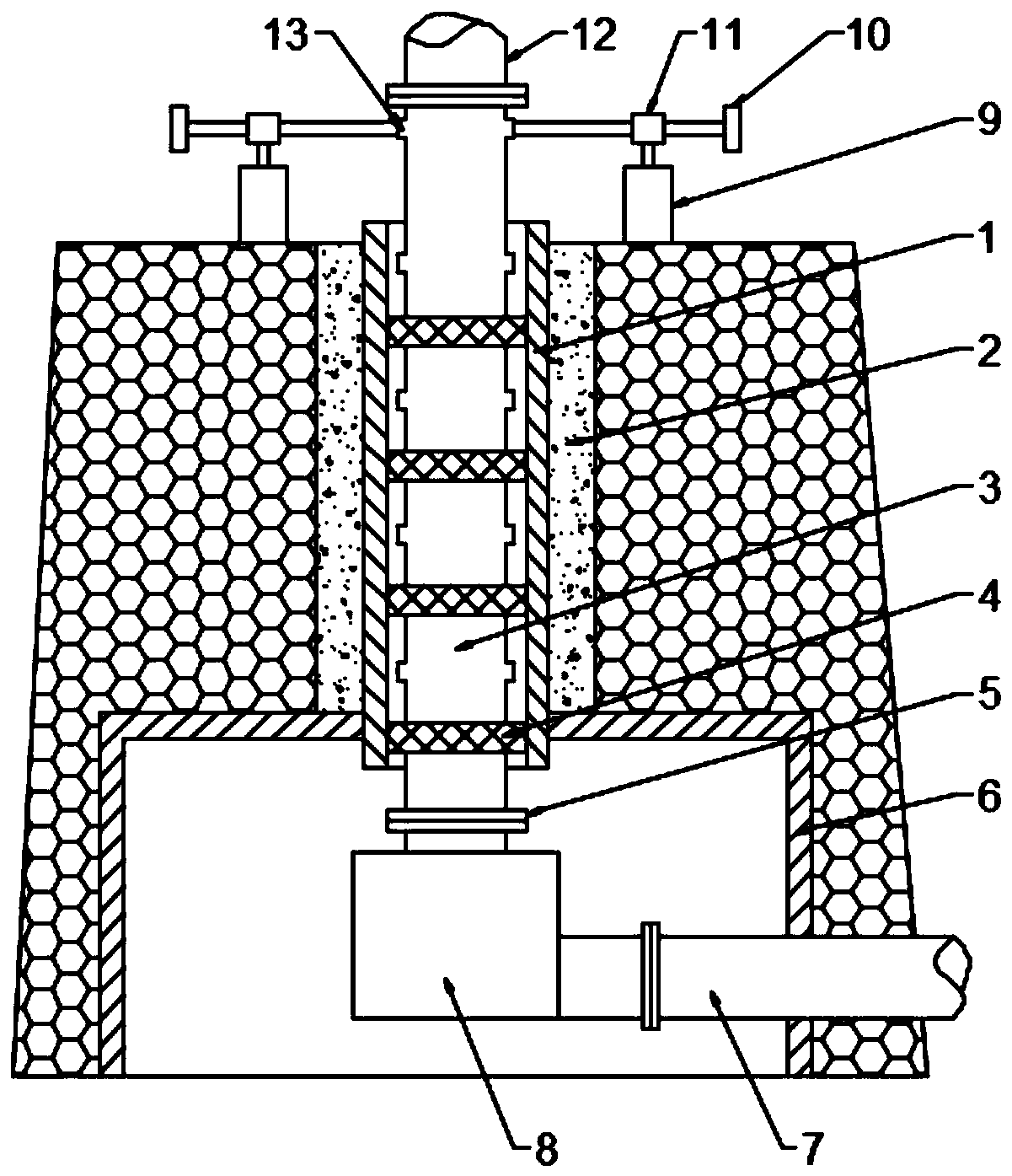
[0019] The present invention will be described in detail below in conjunction with accompanying drawing, as figure 1 Shown: a socketed underground conveying device for tailings paste filling, including a borehole casing 1 fixedly socketed with the borehole and a slurry filling pipe 3 socketed with the borehole casing 1, the The cement layer 2 is filled between the inner wall of the borehole and the outer wall of the borehole casing. The cement layer 2 can not only reliably fix the borehole casing 1, but also play a good role in protecting the borehole and prevent the inside of the borehole from Collapse occurs. A damping ring 4 is arranged between the drilling casing 1 and the slurry filling pipe 3. The vibration damping ring is a wear-resistant rubber damping ring. The vibration damping ring 4 is sleeved on the slurry filling pipe 3 to reduce the The vibrating ring avoids the rigid friction caused by vibration between the drilling casing and the slurry filling pipe.

[0020...


PUM


Abstract

The invention discloses a sleeving type underground conveying device for tailing paste filling. The sleeving type underground conveying device comprises a drilling sleeve fixedly sleeved with a drilled hole and a slurry filling pipe sleeved with the drilling sleeve. The top of the slurry filling pipe is lifted by a lifting mechanism. An underground chamber is constructed at the lower portion of the drilled hole and internally provided with a slurry buffering cavity. The slurry buffering cavity communicates with the bottom of the slurry filling pipe through a flange. One side of the slurry buffering cavity is connected with a downhole filling pipe through a flange. By means of the sleeving type underground conveying device for tailing paste filling, due to the sleeving structural form of the drilling sleeve and the slurry filling pipe, the slurry filling pipe does not make direct contact with the drilled hole, when the slurry filling pipe is abraded to leak, the slurry filling pipe canbe replaced without damaging the drilled hole, the permanent use of the drilled hole is ensured, and filling cost is effectively saved.

Description

technical field [0001] The invention relates to the technical field of tailings paste filling underground conveying pipelines, in particular to a socket-type underground conveying device for tailings paste filling. Background technique [0002] A large amount of solid waste is bound to be generated during the development and utilization of mineral resources. By refilling the remaining solid waste into the underground space, mines can reduce the occurrence of underground space collapse accidents and the pollution of waste to the environment. Among them, the paste filling is mainly to mix one or more solid waste materials, cement and water in a certain proportion and under certain conditions to prepare a paste-like slurry with certain stability, fluidity and plasticity. Under the action of external force or gravity, in the form of plunger flow, it is transported to the underground goaf by pipeline to complete the filling operation. Paste filling technology provides the best w...

Claims


Application Information

Patent Timeline
Patent Type & Authority Applications(China)
IPC IPC(8): E21F15/00
CPCE21F15/00
Inventor 秦杰石泽华李昌元胡中华戴辉
Owner HUNAN CHENZHOU MINING CO LTD
Why Eureka
Try Eureka