

Crude oil conveying pipeline leakage detection system structure and leakage position detection method
A technology for conveying pipelines and leak detection, applied in pipeline systems, mechanical equipment, gas/liquid distribution and storage, etc., can solve problems such as increasing maintenance workload, increasing construction costs, and wasting resources, and is conducive to popularization and application, reducing The effect of maintaining workload and avoiding waste of resources
- Summary
- Abstract
- Description
- Claims
- Application Information
AI Technical Summary
Problems solved by technology
Method used
Image

Examples
specific Embodiment approach
[0036]It should be noted that the structures, proportions, sizes, etc. shown in this specification are only used to match the content disclosed in the specification, for those who are familiar with this technology to understand and read, and are not used to limit the conditions for the implementation of the present invention. Any modification of structure, change of proportional relationship or adjustment of size shall still fall within the scope covered by the technical contents disclosed in the present invention without affecting the functions and objectives of the present invention.
[0037] At the same time, terms such as "upper", "lower", "left", "right", "middle" and "one" quoted in this specification are only for the convenience of description and are not used to limit this specification. The practicable scope of the invention and the change or adjustment of its relative relationship shall also be regarded as the practicable scope of the present invention without any sub...
Embodiment 1
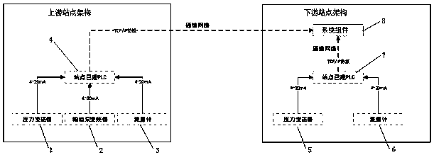
[0040] Such as figure 1 As shown, the present invention discloses a crude oil transmission pipeline leakage detection system framework, including a pipeline upstream station framework and a pipeline downstream station framework, wherein the pipeline upstream station framework includes an upstream pressure transmitter 1, an oil pump frequency converter 2, an upstream flow meter 3 and the upstream site have built PLC 4, in which the upstream pressure transmitter 1, the oil pump frequency converter 2 and the upstream flow meter 3 are respectively set at the upstream site of the pipeline, in which the upstream pressure transmitter 1, the oil pump frequency converter 2, the upstream flow meter Meter 3 is respectively connected to the built PLC 4 of the upstream site, and the downstream site architecture includes a downstream pressure transmitter 5, a downstream flow meter 6, a built PLC 7 of the downstream site and system components 8, wherein the downstream pressure transmitter 5 a...
Embodiment 2
[0042] Such as figure 1 As shown, the present invention discloses a crude oil transmission pipeline leakage detection system framework, including a pipeline upstream station framework and a pipeline downstream station framework, wherein the pipeline upstream station framework includes an upstream pressure transmitter 1, an oil pump frequency converter 2, an upstream flow meter 3 and the upstream site have built PLC 4, in which the upstream pressure transmitter 1, the oil pump frequency converter 2 and the upstream flow meter 3 are respectively set at the upstream site of the pipeline, in which the upstream pressure transmitter 1, the oil pump frequency converter 2, the upstream flow meter Meter 3 is respectively connected to the built PLC 4 of the upstream site, and the downstream site architecture includes a downstream pressure transmitter 5, a downstream flow meter 6, a built PLC 7 of the downstream site and system components 8, wherein the downstream pressure transmitter 5 a...
PUM
 Abstract
Description
Claims
Application Information