Dynamic region division method, region channel identification method and cleaning robot

A dynamic area and robot technology, applied in the field of cleaning robots, can solve the problems that robots cannot make good use of sub-area cleaning, and achieve the effects of reducing the probability of shuttle work, improving cleaning efficiency, and high environmental adaptability

Active Publication Date: 2020-07-28
ECOVACS ROBOTICS CO LTD SUZHOU CITY
23 Cites 9 Cited by

AI-Extracted Technical Summary

Problems solved by technology

However, when the environment changes greatly, the robot may not be able t...

Method used

In the technical solution provided by the present embodiment, the environmental information collected when the robot is working in the first area is obtained, and it is determined that there is a passage into the second area according to the environmental information, and it is judged that the robot has not completed the first area. During the working task, the robot is prevented from entering the second area through the passage, thereby ensuring the principle that a single area can only enter the next area to work after the work is completed, reducing the occurrence probability of repeated scanning and missed scanning, and cleaning efficiency High; in addition, the technical solution provided by this embodiment relies on the environmental information collected in real time during work, without using historical map data, and has high environmental adaptability.
In the technical solution provided by the present embodiment, the environmental information collected when the robot is working in the first area is obtained, and there is a passage to enter the second area according to the environmental information, and it is judged that the robot has not completed the process in the first area. During the working task, the robot is prevented from entering the second area through the passage, thereby ensuring the principle that a single area can only enter the next area to work after the work is completed, reducing the occurrence probability of repeated scanning and missed scanning, and cleaning efficiency High; in addition, the technical solution provided by this embodiment relies on the environmental information collected in real time during work, without using historical map data, and has high environmental adaptability.
In the technical solution provided by this embodiment, the environmental information collected when the robot is working in the first area is obtained, and it is determined that there is a passage into the second area according to the environmental information, and at the same time it is determined that the robot has not completed the first area. During the working task, the robot is prevented from entering the second area through the passage, thereby ensuring the principle that a single area can only enter the next area to work after the work is completed, reducing the occurrence probability of repeated scanning and missed scanning, and cleaning efficiency High; in addition, the technical solution provided by this embodiment relies on the environmental information collected in real time during work, without using historical map data, and has high environmental adaptabil...

Abstract

The embodiment of the invention provides a dynamic region division method, a region channel identification method and a cleaning robot. The dynamic region division method comprises the following stepsthat: environmental information collected by a robot is acquired when the robot works in a first region; when it is determined that a channel entering a second region exists based on the environmentinformation, whether the robot completes a working task in the first region or not is judged; and when the working task is not completed, a boundary at the channel is supplemented to block the channel. According to the technical scheme provided by the embodiment of the invention, the probability of repeated sweeping and missed sweeping is reduced, and the cleaning efficiency is high; besides, themethod provided by the technical schemes of the embodiment depends on the environmental information collected in work without the help of historical map data, so that environmental adaptability is high.

Application Domain

Technology Topic

RobotyEnvironmental adaptation +4

Image

  • Dynamic region division method, region channel identification method and cleaning robot
  • Dynamic region division method, region channel identification method and cleaning robot
  • Dynamic region division method, region channel identification method and cleaning robot

Examples

  • Experimental program(1)

Example Embodiment

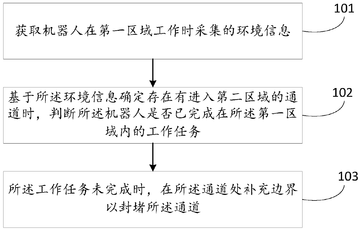
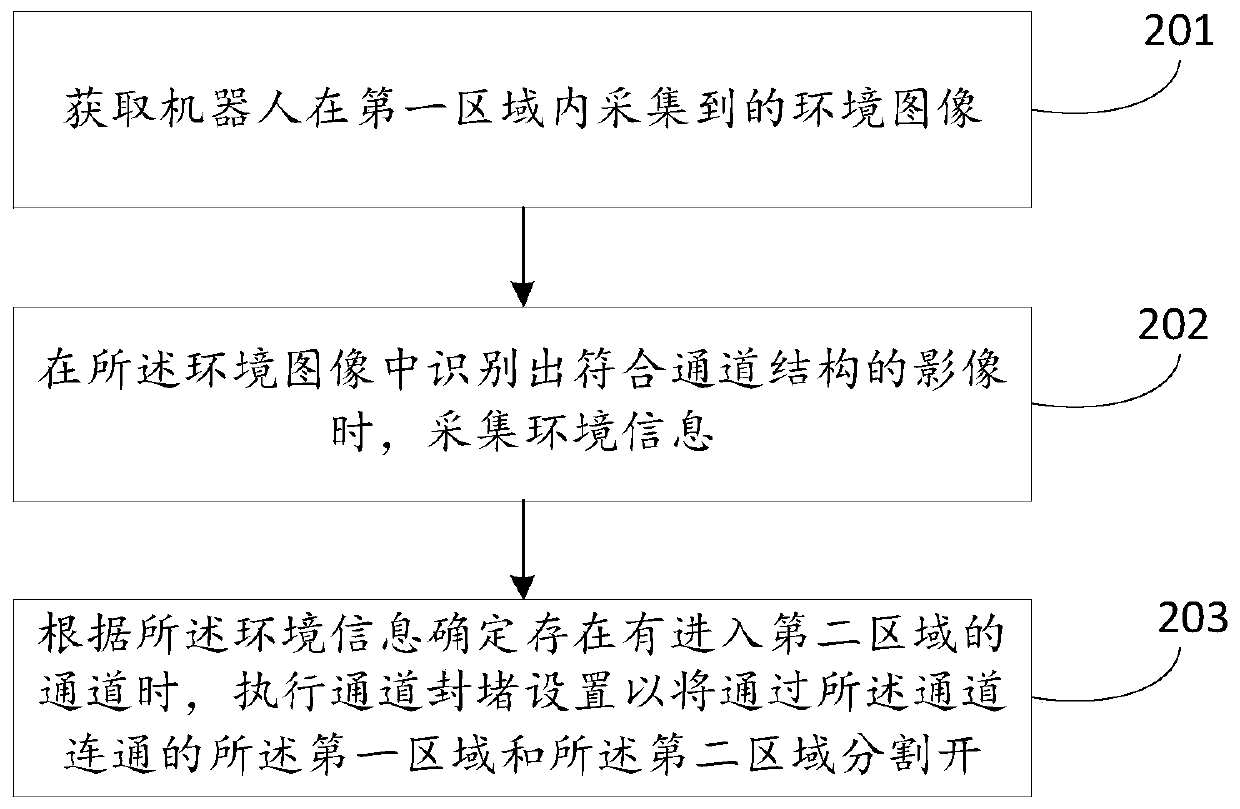
[0051] Cleaning robots, such as sweeping robots, when cleaning in the home, complete the cleaning by traversing the entire apartment area. If it is impossible to distinguish between different rooms and clean separately, the robot will repeatedly enter and exit the same room, or alternate between different rooms, and it will need to enter and exit multiple times to complete the cleaning task of a room, which directly leads to low cleaning efficiency; indirectly Repeated scans, missed scans, etc., even the entire house cannot be cleaned completely. In order to solve the above problems, it is necessary to identify the room and follow the principle of cleaning a single room before entering the next room.
[0052] There is a static partitioning scheme in the prior art. Static partitioning scheme, that is, after the cleaning robot completes at least one cleaning, it can outline the house map of the entire house; then the house map is partitioned to divide different rooms, and the robot will use the divided room when it works next time. Map data. The static partitioning scheme is poorly adaptive, and the existing map data cannot be used when the environment changes.
[0053] In order to enable those skilled in the art to better understand the solutions of the present application, the technical solutions in the embodiments of the present application will be described clearly and completely in conjunction with the accompanying drawings in the embodiments of the present application.
[0054] Some processes described in the specification, claims, and the above-mentioned drawings of the present application include multiple operations appearing in a specific order, and these operations may be performed out of the order in which they appear in this document or performed in parallel. The sequence numbers of operations such as 101 and 102 are only used to distinguish different operations, and the sequence numbers themselves do not represent any execution order. In addition, these processes may include more or fewer operations, and these operations may be executed sequentially or in parallel. It should be noted that the descriptions of "first" and "second" in this article are used to distinguish different messages, devices, modules, etc., and do not represent a sequence, nor do they limit the "first" and "second" Are different types. In addition, the embodiments described below are only a part of the embodiments of the present application, rather than all the embodiments. Based on the embodiments in this application, all other embodiments obtained by those skilled in the art without creative work shall fall within the protection scope of this application.
[0055] figure 1 It shows a flow chart of a method for dynamic area division provided by an embodiment of the present application. As shown in the figure, the method provided in this embodiment includes:
[0056] 101. Acquire environmental information collected when the robot is working in the first area.
[0057] 102. When it is determined based on the environment information that there is a passage to enter the second area, determine whether the robot has completed the work task in the first area.
[0058] 103. When the work task is not completed, supplement a boundary at the channel to block the channel.
[0059] In the above 101, the environmental information may be two-dimensional point cloud data collected by a sensor (such as a laser sensor, etc.) installed on the robot after scanning an obstacle in a plane; or a visual sensor ( For example, a sensor module of a monocular camera, a binocular camera, a depth camera (RGBD, etc.) collects three-dimensional point cloud data, etc., which is not specifically limited in this embodiment.
[0060] In the above 102, the passage refers to the passage through which the robot can pass through the two areas, such as a doorway. Taking door openings as an example, door openings have certain characteristics, such as shape and size characteristics. Therefore, in specific implementation, it can be determined based on the environmental information whether there is a channel that meets the channel characteristics (such as shape characteristics and size characteristics) in the actual working scene of the robot.
[0061] Whether the robot has completed the work task in the first area can be determined by the work record of the robot in the first area. The work record may include but is not limited to: work mode (such as bow-shaped cleaning mode, zig-zag cleaning mode, etc.), starting position, and the current position of the robot. Suppose, such as Figure 5 As shown, the working mode of the robot is the bow-shaped cleaning mode, and the starting position is the area map in the first area ( Figure 5 Middle room 1) A certain position in the middle. The robot works from the starting position to Figure 5 The current position shown in. These information can be recorded, and then based on the robot’s Figure 5 The work record in room 1 shown in Figure 1 determines whether the robot has completed its work task in room 1.
[0062] In the technical solution provided by this embodiment, the environment information collected when the robot is working in the first area is acquired, and it is determined according to the environment information that there is a channel to enter the second area, and at the same time, it is determined that the robot has not completed the work task in the first area. At this time, the robot is prevented from entering the second area through the passage, thereby ensuring the principle of entering the next area after the work of a single area is completed, reducing the probability of repeated scanning and missing scanning, and has high cleaning efficiency; , The technical solution provided by this embodiment relies on the environmental information collected in real time during work without using historical map data, and has high environmental adaptability.
[0063] In an achievable technical solution, the environmental information is a point cloud model. Correspondingly, the above 101 may include:
[0064] 1011. Collect an environment image when the robot is working in the first area.
[0065] 1012. Recognize the environmental image.
[0066] 1013. When it is recognized that the environment image contains an image that conforms to the channel structure, the point cloud model is constructed for the surrounding environment of the robot by using Simultaneous Localization and Mapping (SLAM) technology.
[0067] Wherein, the environment image can be collected by a vision sensor set on the robot. The recognition of environmental images can include but is not limited to the following methods:
[0068] Method 1: Using the deep learning method, the deep learning training model is trained through a large number of samples to obtain a recognition model; then the environment image is used as the input of the recognition model, and the recognition model is executed to obtain that the environment image contains a matching channel The output result of the structured image.
[0069] Method 2: Use the image pattern matching method to compare the environment image with the preset channel structure image. If the comparison is successful, it is determined that the environment image contains images that conform to the channel structure; otherwise, it is determined that the environment image is Does not contain images that conform to the channel structure.
[0070] SLAM technology refers to a technology in which a robot can determine its own spatial position through sensor information in an unknown environment and establish an environment model of the space in which it is located. Using SLAM technology, the robot can carry sensors to patrol the environment for a week to construct an environmental map. The operation is simple. With the advancement of sensor accuracy and technology, the accuracy of maps constructed using SLAM technology has gradually improved. The SLAM method mostly uses laser or sonar to generate a two-dimensional point cloud model to create a two-dimensional map. Since the laser scanning range is limited to a single plane, in order to fully represent the complex structure in the environment, vision-based SLAM technology (VSLAM for short) can be used to generate a 3D point cloud model using a vision sensor to construct a 3D map.
[0071] That is, the point cloud model in 1013 in this embodiment may be a two-dimensional point cloud model constructed by using SLAM technology, or a three-dimensional point cloud model constructed by using VSLAM technology.
[0072] Further, the environment information is a point cloud model. Accordingly, the method provided in this embodiment may further include the following steps:
[0073] 104. Based on the point cloud model, obtain size information of candidate structures that conform to the channel structure.
[0074] 105. When the size information meets a preset size requirement, it is determined that the candidate structure is a channel to enter the second area.
[0075] Among them, since size information is recorded in the point cloud model, the size information of the candidate structure conforming to the channel structure can be obtained based on the point cloud model. In specific implementation, the size information may include: width, height, and depth. In an achievable technical solution, the preset size requirements include a width interval, a height interval, and a depth interval; if the width included in the size information is within the width interval, and the height is within the height interval If the depth is within the depth interval, the size information meets the preset size requirement. Through the above steps 104 and 105, real passages (such as door openings) can be screened out, false alarms can be deleted, and misrecognition of some situations similar to the passage structure such as cabinets and wall paintings can be avoided.
[0076] In another achievable technical solution, the environmental information is two-dimensional point cloud data collected by a laser sensor on the robot after scanning an obstacle in a plane. Correspondingly, the method provided in this embodiment may also adopt the following method to determine whether there is a passage from the first area to the second area based on the environmental information. Wherein, the method of determining whether there is a passage from the first area into the second area based on environmental information includes: firstly, based on the two-dimensional point cloud data, identifying whether there is a gap (Gap) in the first area that conforms to the structure of the passage; if There is a gap that conforms to the channel structure, and according to the barrier boundaries on both sides of the left and right ends of the gap, it is recognized whether the gap is a channel that enters the second area from the first area.
[0077] Among them, an optional way to identify gaps (Gap) is: based on two-dimensional point cloud data, search for obstacles in the area ahead of the robot; if adjacent obstacles are found in the front area, calculate the robot and adjacent obstacles The formed angle; if the angle is greater than the set angle threshold, calculate the distance between adjacent obstacles; if the distance between adjacent obstacles meets the set distance requirement, determine the distance between adjacent obstacles There is a gap in line with the channel structure.
[0078] It should be noted that in the embodiment of the present application, the range of the front area is not limited, and it can be flexibly set according to the application scenario. Similarly, in the embodiments of the present application, the included angle threshold and distance requirements are not limited, and can be flexibly set according to application requirements. The front area, included angle threshold, and distance requirements can be interrelated and affect each other. Taking an application scenario that includes a door hole as an example, if the width of the door hole is 70-120cm (centimeters), the above-mentioned front area can be 1m (meters) in front of the robot and within 90 degrees on the left and right sides. Accordingly, the included angle threshold can be 110 degrees, the distance requirement can be a distance range, such as 70-120cm. In this scenario, the way to identify gaps (Gap) is: search for obstacles within 1m in front of the robot in the range of 90 degrees left and right; if an adjacent obstacle is found, calculate the angle formed by the robot and the adjacent obstacle; if If the included angle is greater than 110 degrees, calculate the distance between adjacent obstacles; if the distance between adjacent obstacles is between 70-120 cm, it is determined that there is a gap between the adjacent obstacles that conforms to the channel structure.
[0079] Furthermore, in order to reduce the rate of misjudgment, the number of obstacles in the specified range around the gap (Gap) can also be calculated, and the number of obstacles in the specified range around the gap (Gap) can be used to assist in judging whether the gap between the above adjacent obstacles is Meet the channel structure. For different channel structures, according to the number of obstacles in the specified range around the gap (Gap), the implementation manners for assisting in determining whether the gap conforms to the channel structure will be different. Assuming that the channel structure is a doorway structure, there are generally not many obstacles around the doorway structure. Based on this, it can be judged whether the number of obstacles in the specified range around the gap meets the set number requirements, such as whether it is less than the set obstacle If it meets the threshold of the quantity of objects, it is determined that the gap conforms to the channel structure; if not, it is determined that the gap does not conform to the channel structure.
[0080] In a specific embodiment, the location of the robot may be taken as the center, and the number of obstacles in the front area, the back area, the left area, and the right area of ​​the robot are calculated as the number of obstacles in the specified range around the gap (Gap). Optionally, the range of the front area, the rear area, the left area and the right area can be flexibly set according to the application scenario, for example, each area can be a square area of ​​1m*1m, 1.5m*1.5m, or 1m *1.5m rectangular area can also be a fan-shaped area with a radius of 1m, etc. Further, the threshold of the proportion of obstacles in the front area (denoted as the first proportion threshold) and the threshold of the proportion of obstacles in the rear area (denoted as the second proportion threshold) can be preset to calculate the obstacles in the area in front of the robot The first ratio of the number to the sum of the number of obstacles in the front, rear, left, and right areas, and calculate the second ratio of the number of obstacles in the area behind the robot to the sum of the number of obstacles in the four areas; The ratio and the second ratio are respectively compared with the first and second ratio thresholds; if the first ratio is less than the first ratio threshold and the second ratio is less than the second ratio threshold, it is determined that the gap meets the channel Structure; on the contrary, in other cases, it is determined that the gap does not conform to the channel structure. In this embodiment, the values ​​of the first ratio threshold and the second ratio threshold are not limited, and the values ​​of the two may be the same or different, and can be flexibly set according to the application scenario. For example, the first ratio threshold may be, but not limited to: 1/2, 1/3, 1/5, etc.; the second ratio threshold may be 2/3, 1/3, 1/4, 2/5, etc.
[0081] After determining that there is a gap (Gap) conforming to the channel structure in the first area, it can be identified whether the gap is a channel from the first area into the second area according to the barrier boundaries on both sides of the left and right end points of the gap. Wherein, according to the obstacle boundaries on both sides of the left and right ends of the gap, it is recognized whether the gap is a passage from the first area into the second area. An optional implementation includes: if the obstacle boundaries on both sides of the left and right ends of the gap meet the design If the boundary requirements are set, it is determined that the gap is a passage from the first area to the second area; if the boundary of the obstacles on both sides of the gap does not meet the set boundary requirements, it is determined that the gap does not enter the second area from the first area. The passage of the second area.
[0082] Depending on the channel structure, the boundary requirements will vary. In an optional embodiment, the boundary requirement means that when the boundary of the obstacle on both sides of the left and right ends of the gap is parallel or approximately parallel, the gap belongs to the channel; otherwise, the gap does not belong to the channel. Based on this, it can be specifically judged whether the obstacle boundaries on both sides of the gap are parallel or approximately parallel. If parallel or approximately parallel, it is determined that the gap is a passage from the first area to the second area; otherwise, it is determined that the gap is not The passage from the first zone to the second zone.
[0083] In the above embodiment, the obstacle boundaries on both sides of the left and right endpoints of the gap refer to the continuous obstacle boundaries within a certain area, and usually include multiple boundary points instead of only one boundary point. In some application scenarios, the laser sensor on the robot can collect continuous obstacle boundaries in a certain area on both sides of the left and right ends of the gap, and can directly determine whether the obstacle boundaries on both sides of the gap are parallel or approximately parallel.
[0084] In other application scenarios, due to the angle problem, the laser sensor on the robot may not be able to collect continuous obstacle boundaries in a certain area on both sides of the left and right ends of the gap, and it collects some discrete or discontinuous boundary points. In view of this scenario, an embodiment for identifying whether the gap is a passage from the first area to the second area includes: performing expansion and corrosion in a certain area on both sides of the left and right ends of the gap (called the first set area range) , Get the continuous obstacles on both sides of the gap; track the boundary of the continuous obstacles on both sides of the gap (referred to as the obstacle boundary) in the second set area, and calculate the obstacle boundary on both sides of the gap. According to the two slopes, judge whether the barriers on both sides of the gap are parallel or approximately parallel; if so, it is determined that the gap is a passage from the first area to the second area; otherwise, it is determined that the gap is not from The first zone enters the second zone.
[0085] Optionally, it can be determined whether the difference between the two slopes is within the set difference range, and if so, it is determined that the barriers on both sides of the left and right ends of the gap are parallel or approximately parallel. The difference range can be flexibly set according to application requirements, for example, it can be 0-0.01 or 0-0.05.
[0086] In this embodiment, the first set area range and the second preset area range are not limited, and can be set flexibly. In an optional embodiment, the robot can construct a regional topology map in real time based on the two-dimensional point cloud data collected by the laser sensor, and the first preset area range and the second preset area range can be determined by the map information in the regional topology map. Qualify. Optionally, the regional topology map may be a grid map, and the first set area range and the second preset area range may be defined by the number of grids in the grid map. For example, the first set area range may be 10, 15, 20, or 30 grid ranges with the left and right end points of the gap as the starting points, respectively, where the number of grids 10, 15, 20, or 30 is only an exemplary illustration. Correspondingly, the second preset area range may be 4 neighborhoods, 8 neighborhoods, 12 neighborhoods, etc. centered on the location of the robot.
[0087] Based on the above concept of grid map, the boundary of obstacles can be tracked within the second preset area. If the number of grids is tracked in the second preset area, the number of grids is greater than the set threshold of grid number (for example, 4 grids ), it is determined that the obstacle boundary is tracked; otherwise, it is determined that the obstacle boundary tracking fails. In case of failure, the partition operation can be ended.
[0088] Further optionally, in order to reduce the misjudgment rate, after determining that the boundaries of the obstacles on both sides of the gap are parallel or approximately parallel, at least one of the following judgment operations may be performed:
[0089] Operation 1: Determine whether the vector of the obstacle boundary on at least one side of the gap, the vector of the intersection boundary of the second area, and the vector of the undetected area adjacent to the second area are in the same clockwise direction;
[0090] Operation 2: Determine whether the angle between the boundary of the obstacle on at least one side of the gap and the intersection boundary of the second area is within the set angle range;
[0091] Operation 3: Determine whether the tracking start point of the intersection boundary of the second area is in the same connected area as the robot;
[0092] Operation 4: Determine whether the obstacles on both sides of the gap are not isolated obstacles.
[0093] If the judgment result of the above at least one judgment operation is yes, it is determined that the gap is a passage from the first area to the second area; otherwise, it is determined that the gap is not a passage from the first area to the second area.
[0094] In operation 1, the barrier boundary, the intersection boundary of the second area, and the undetected area adjacent to the second area refer to the boundary or area on the same side of the gap, for example, the boundary or area located on the left side of the gap. Or it is the border or area on the right side of the gap. Wherein, the intersection boundary of the second area refers to the boundary between the second area and its adjacent undetected area, and the boundary intersects the left or right end of the gap. Wherein, the intersection boundary of the second area can be tracked within the scope of the third set area. On the basis of the grid map, the third set area range can also be defined by the number of grids. For example, the left end or the right end of the gap may be used as the starting point, and 5, 10, 15 or 20 grid areas in the extending direction of the second area may be defined as the third set area range. Among them, the number of grids of 5, 10, 15 or 20 is only an exemplary illustration.
[0095] In operation 1, the vector of the obstacle boundary on the left side of the gap refers to the vector from the left end of the gap to the right end; the vector of the obstacle boundary on the right side of the gap refers to the vector from the right end of the gap to the left end; Ground, the vector of the intersection boundary of the second area on the left of the gap refers to the vector from the left end of the gap to the intersection boundary of the second area on the left of the gap; the vector of the intersection boundary of the second area on the right of the gap is Refers to the vector pointing from the right end of the gap to the intersection boundary of the second area on the right side of the gap; correspondingly, the vector of the undetected area adjacent to the second area on the left side of the gap refers to the vector from the left end of the gap to the left of the gap The vector of the undetected area adjacent to the second area on the side; the vector of the undetected area adjacent to the second area on the right side of the gap refers to the vector from the right end of the gap to the adjacent area on the right side of the gap The vector of the undetected area.
[0096] In operation 1, the three vectors on the left side of the gap can be in the same clockwise direction (clockwise or counterclockwise), or the three vectors on the right side of the gap can be in the same clockwise direction (clockwise or counterclockwise). ), or alternatively, the three vectors on the left side of the gap and the three vectors on the right side of the gap are in the same clockwise direction. See Picture 10 , The three vectors on the left side of the gap (ie Picture 10 The three lines with arrows in the middle) follow the clockwise direction.
[0097] In operation 2, it can be judged whether the angle between the boundary of the obstacle on the left of the gap and the boundary of the second area on the left of the gap is within the left angle range; it can also be judged whether the boundary of the obstacle on the right of the gap is Whether the angle of the intersection boundary of the second area on the right side of the gap is within the right angle range; it can also be judged at the same time whether the angle between the boundary of the obstacle on the left side of the gap and the boundary of the second area on the left side of the gap is included Within the left angle range, and determine whether the angle between the boundary of the obstacle located on the right side of the gap and the intersection boundary of the second area located on the right side of the gap is within the right angle range.
[0098] Among them, the left angle range and the right angle range may be the same or different, and can be flexibly set according to application requirements. For example, the left angle range may be 10-85 degrees, and the right angle range may be 95-170 degrees, but it is not limited to this.
[0099] In operation 3, the connected area refers to a certain area including the left and right endpoints of the gap, and the area range can be flexibly determined. The tracking starting point of the intersection boundary of the second area refers to the starting point of tracking to the intersection boundary of the second area.
[0100] In operation 4, it can also be determined whether the obstacles on both sides of the gap are the same obstacle with the gap. For example, the gap may be a door opening of a room, and the obstacles on both sides of the door opening are four walls in the same room, and the four walls are continuous and integrated, and are not isolated obstacles.
[0101] Further, when it is determined that the gap is a passage from the first area to the second area, the coordinates of the left and right end points of the gap can also be output, so that the user or the robot can determine the position of the passage from the first area to the second area.
[0102] No matter what method is adopted, after determining that there is a passage into the second area, in specific implementation, step 103 in the method provided in this embodiment may include but is not limited to the following solutions:
[0103] In an achievable solution, the foregoing step 103 may specifically include:
[0104] 1031. Acquire a regional topology map and the position of the channel in the regional topology map;
[0105] 1032. At the location on the regional topology map, supplement a boundary to block the passage.
[0106] In a specific implementation, the above 1032 may specifically be: adding a virtual wall at the location of the regional topological map; wherein the virtual wall is a boundary shape that can block the passage. The virtual wall is impassable to the robot. Optionally, the virtual wall may or may not be displayed on the regional topology map. or
[0107] The above 1032 may specifically be: setting a channel blocking attribute at the location on the regional topological map; wherein, the channel with the blocking attribute set is not passable by the robot. Setting the channel blocking attribute is another way to supplement the boundary.
[0108] Correspondingly, the method provided in this embodiment may further include:
[0109] 106. When the work task in the first area is completed, cancel the boundary supplemented at the passage.
[0110] Similarly, the above 106 may specifically be: deleting the virtual wall at the position on the regional topology map; or
[0111] The foregoing 106 may specifically be: deleting the channel blockage attribute at the location on the regional topology map.
[0112] Further, after step 103, the method provided in this embodiment may further include the following steps:
[0113] 1031'. Obtain the work record of the robot in the first area.
[0114] 1032'. Determine the connection plan according to the work record.
[0115] 1033'. According to the connection plan, control the robot to continue working in the first area.
[0116] In the above 1031', the work record includes, but is not limited to: working mode, starting position, the starting direction of the robot at the starting position, and the halfway position when the robot is monitored to work to the passage . Correspondingly, the above step 1031' may specifically be: acquiring an area map of the first area; determining the area map according to the area map, the working mode, the starting position, the starting direction, and the midway position. Describe the connection plan.
[0117] The above step 1032' may be specifically: planning a path to return to the starting position according to the midway position; controlling the robot to work to return to the starting position according to the path; according to the starting direction, Adjusting the connection orientation of the robot after returning to the starting position again; controlling the robot to follow the connection orientation from the starting position to continue working in the first area in the working mode.
[0118] See Figure 4 with 5 In the example shown, the robot adopts a bow-shaped working mode. When the robot moves to the channel ( Figure 4 It can continue to move in the current direction (ie the current orientation of the robot) to the boundary position of room 1, and then return from the boundary position to the starting position along a straight line. From Figure 4 It can be seen that the starting direction of the robot is the positive X direction in the figure, and the adjusted connection direction is the negative X direction which is opposite to the positive X direction, such as Figure 5 Shown. Finally, control the robot to continue to work in room 1 along the negative X direction from the starting position in a bow-shaped work mode.
[0119] Further, the method provided in the embodiment of the present application may further include:
[0120] 106'. When the work task is completed, control the robot to move from the end position when the work task is completed to the halfway position, and control the robot to pass through the halfway position after the robot reaches the halfway position. The passage enters the second area.
[0121] The solution of 106 above is to prevent the robot from entering the second area through the passage from the perspective of setting the area topology map; the solution of step 106' is to prevent the robot from entering the second area through the passage from the perspective of the robot's control strategy. The second area.
[0122] figure 2 It shows a schematic flow chart of a dynamic area division method provided by an embodiment of the present application. Such as figure 2 As shown, the dynamic area division method includes:
[0123] 201. Acquire an environment image collected by a robot in a first area.
[0124] 202. Collect environmental information when an image conforming to the channel structure is identified in the environmental image.
[0125] 203. When it is determined according to the environmental information that there is a passage into the second area, perform passage blocking setting to separate the first area and the second area connected through the passage.
[0126] In the above 201, the environment image may be collected by the vision sensor on the robot.
[0127] For the method of identifying images that conform to the channel structure in the environmental image in the above-mentioned 202, please refer to the corresponding content in the above-mentioned embodiment, which will not be repeated here.
[0128] In the above 202, the environment information is a point cloud model. Correspondingly, this step 202 may specifically include: constructing the point cloud model for the surrounding environment of the robot by using the simultaneous positioning and map creation SLAM technology.
[0129] The point cloud model may be a two-dimensional point cloud model constructed based on SLAM technology, or a three-dimensional point cloud model constructed based on VSLAM technology.
[0130] Similarly, in this embodiment, for the process of determining whether there is a passage into the second area according to the environmental information, please refer to the relevant content in the foregoing embodiment, which will not be repeated this time.
[0131] Further, the dynamic area division method provided in this embodiment may further include:
[0132] 204. When the channel opening event is monitored, perform channel opening setting to connect the first area and the second area through the channel.
[0133] Wherein, during specific implementation, the trigger mode of the open channel event includes at least one of the following:
[0134] Triggering the open channel event when it is determined based on the task execution status of the robot in the first area that the robot has completed its task in the first area;
[0135] After receiving the open channel instruction input by the user, the open channel event is triggered.
[0136] Wherein, the open channel instruction may be generated after the user touches the corresponding control key on the cleaning robot, or generated after the user operates the map on the man-machine interface of the cleaning robot, or the user points to the cleaning robot. Generated after the robot sends out the control voice.
[0137] In the technical solution provided by this embodiment, the environment image collected by the robot in the first area is acquired, and the environment information is collected when the image that conforms to the channel structure is recognized in the environment image; if it is determined that there is an entry into the second area according to the environment information In the passage, the first area and the second area connected by the passage are divided to divide the work area in real time, reduce the probability of the robot shuttle working across the area, realize the dynamic partition, and help improve the cleaning efficiency.
[0138] In some embodiments of the present application, a vision sensor is provided on the robot, and the vision sensor can collect environment images when the robot is working. The technical solutions provided by these embodiments can be simply understood as: after identifying images that conform to the channel structure in the environmental images collected by the vision sensor, the three-dimensional information (such as three-dimensional point cloud model) provided by SLAM technology is used to determine the actual work of the robot Whether there is a cross-domain channel in the scene; when there is a channel, one is to directly control the robot to reach the channel position when the robot works, and it will not pass through the channel until the work task in the first area is completed The function of entering the next area through the channel to perform tasks; the other is to modify the regional topology map, that is, the way to block the channel at the location of the channel of the regional topology map (such as adding a virtual wall) to achieve the robot's work. When the channel is located, it will not pass through the channel until the task in the first area is completed before entering the next area through the channel to perform the task.
[0139] In some other embodiments of the present application, a laser sensor is provided on the robot, and the laser sensor can collect surrounding environment information, that is, two-dimensional point cloud data when the robot is working. The technical solutions provided by these embodiments can be simply understood as: According to the two-dimensional point cloud data collected by the laser sensor, determine whether there is a cross-domain channel in the actual working scene of the robot; when there are channels, one is through direct control The way of the robot is to achieve the function of the robot working to the channel position, it will not pass through the channel, until the task of the first area is completed, the channel enters the next area to perform the task; the other is to modify the regional topology map , That is, the way to block the channel at the location of the channel on the regional topology map (such as adding a virtual wall), so that when the robot works to the channel position, it will not pass through the channel until the task in the first area is completed. The function of entering the next area through the channel to perform the task.
[0140] The technical solutions provided by the embodiments of the present application do not require historical map data. When the robot cleans for the first time or again in an unfamiliar environment, the robot can be dynamically controlled in real time or the regional topology map can be set accordingly, so that The robot achieves dynamic partitioning, which can perform tasks according to different areas, reduce the probability of repeated or missed scanning, and improve cleaning efficiency. In addition, the technical solution provided by the embodiments of the present application utilizes the existing vision sensor on the robot without additional sensors, which reduces costs, reduces the difficulty of structural design, and has good real-time performance.
[0141] The technical solutions provided by the embodiments of the present application can be applied to all household robot products with vision sensors (such as sweeping robots). The technical solutions provided by the embodiments of the present application will be described below in combination with specific application scenarios.
[0142] When the sweeping robot is cleaning in the home environment, it can recognize the channel in real time (such as Figure 4 No. 1 to No. 4 door, corridor entrance, etc. shown in), and according to the 3D information provided by SLAM (such as 3D point cloud model) Figure 4 In the topological map of the indoor room shown, the channel blocking setting (such as setting a virtual wall) is performed at the location of the channel, so that the sweeping robot can perform tasks in different areas.
[0143] What needs to be explained here is that the setting of the virtual wall is dynamic. That is, assuming that the robot is currently in room 1 (e.g. Figure 4 Shown), when the robot works in room 1 to Figure 4 It is determined that there is a cross-domain channel ( Figure 4 In the case of door 1), only the channel corresponding to door 1 will be blocked; after the robot has cleaned room 1, the channel corresponding to door 1 needs to be opened (such as deleting Virtual wall) so that the robot can enter the corridor through door 1.
[0144] Robot D enters an unfamiliar environment for the first time image 3 As shown, they are randomly placed anywhere, such as image 3 Put it in room 1, no matter what cleaning method is used to start. If you start cleaning in a bow shape, such as Figure 4 As shown, the robot will recognize in real time whether there is a channel when it is working; when the robot is working to the channel, when it has not determined that the cleaning of room 1 is completed, it will return to the starting position and complete the remaining part of the cleaning according to the cleaning strategy until it is determined After completing the cleaning task of room 1, the robot will pass through door 1, such as Figure 5 Shown, proceed to the next area ( Figure 5 In the corridor), in the example floor plan, the robot will enter the corridor to perform the cleaning task.
[0145] Such as Image 6 As shown, in the process of working in the corridor area, the robot will also dynamically recognize whether there is a channel (such as Image 6 Doors No. 1 to No. 4, corridor entrances, etc. as shown in), and work to the corresponding passage, when it is not sure to clean the corridor, it will not pass through the passage to enter other areas, and will complete the remaining areas according to the cleaning strategy Partial cleaning until it is determined that the cleaning task of the current area (ie corridor area) is completed, and then the machine will select an area from the area that has not been cleaned according to the cleaning strategy, and then pass through the channel corresponding to the selected area to proceed to the next Area cleaning tasks.
[0146] The technical solutions provided by the embodiments of the present application can be applied to all household robot products (such as sweeping robots) with laser sensors. The technical solutions provided by the embodiments of the present application will be described below in combination with specific application scenarios.
[0147] Robot D enters an unfamiliar environment for the first time Picture 10 As shown, they are randomly placed anywhere, such as Picture 10 It indicates that it is placed in a certain position in the living room 6, no matter what cleaning method is used to start. If the cleaning is started in a bow-shaped manner, during the cleaning process, the robot D can use the laser sensor to collect environmental information in the working environment in real time, that is, two-dimensional point cloud data. Picture 10 The black solid line shows the wall, and the black dotted line shows the movement trajectory of the robot D. Based on the two-dimensional point cloud data collected by the laser sensor, a regional grid map can be constructed, such as Picture 10 Shown. in Picture 10 In the beginning, since the room 5 and the living room 6 were not partitioned at the beginning, the robot D moves to the passage ( Picture 10 At the gap shown in), you can enter room 5 to continue cleaning tasks and continue to build a grid map. Further, in the process of performing cleaning tasks in room 5, if robot D collects the channel between room 5 and living room 6 again, it can follow Picture 11 The illustrated method recognizes the passage between the room 5 and the living room 6 (such as a door opening).
[0148] Further, when the robot D works to the passage, when it is determined that the room 5 has not been cleaned, it can Picture 10 In the grid map shown, the channel block setting (such as setting a virtual wall) is performed at the location of the channel in order to continue cleaning the remaining part of the room 5 until it is determined that the cleaning task of the room 5 is completed, and the robot D will pass through the channel Enter the living room 6 to continue cleaning tasks. For the description of the virtual wall, please refer to the foregoing scenario embodiment, which will not be repeated here.
[0149] In the foregoing embodiment, the technical solution of the present application is exemplified by taking a robot that can perform a sweeping task (referred to as a sweeping robot) as an example, but it is not limited to a sweeping robot. The robot in the embodiments of this application generally refers to any mechanical equipment that can move in space with a high degree of autonomy in its environment, for example, it can be a sweeping robot, an escort robot, or a guiding robot, etc., or a purifier or unmanned driving. Vehicles etc. Of course, for different robot forms, the tasks they perform will be different, and there is no limitation on this.
[0150] Figure 7 It shows a schematic structural diagram of a dynamic area dividing apparatus provided by an embodiment of the present application. Such as Figure 7 As shown, the device includes: a first acquisition module 11, a judgment module 12, and a supplementary module 13. Wherein, the first acquisition module 11 is used to acquire environmental information collected when the robot is working in the first area; the judgment module 12 is used to judge when it is determined that there is a passage into the second area based on the environmental information Whether the robot has completed the work task in the first area; the supplementary module 13 is used to supplement the boundary at the passage to block the passage when the work task in the first area is not completed.
[0151] In the technical solution provided by this embodiment, the environment information collected when the robot is working in the first area is acquired, and it is determined according to the environment information that there is a channel to enter the second area, and at the same time, it is determined that the robot has not completed the work task in the first area. At this time, the robot is prevented from entering the second area through the passage, thereby ensuring the principle of entering the next area after the work of a single area is completed, reducing the probability of repeated scanning and missing scanning, and has high cleaning efficiency; , The technical solution provided by this embodiment relies on the environmental information collected in real time during work without using historical map data, and has high environmental adaptability.
[0152] Further, the environment information is a point cloud model; and the first acquisition module 11 is also used to: collect an environment image when the robot is working in the first area; identify the environment image; and identify the When the environment image contains images conforming to the channel structure, the simultaneous positioning and map creation SLAM technology is used to construct the point cloud model of the surrounding environment of the robot.
[0153] Further, the device provided in this embodiment further includes a second acquiring module and a determining module. Wherein, the second obtaining module is used to obtain the size information of the candidate structure conforming to the channel structure based on the point cloud model; the determining module is used to determine that the candidate structure is entered when the size information meets the preset size requirement. Channel in the second area.
[0154] Further, the size information includes: width, height and depth.
[0155] Further, the supplementary module 13 is further configured to: obtain a regional topology map and the location of the channel in the regional topology map; and perform channel blocking settings at the location of the regional topology map.
[0156] Further, the supplementary module 13 is also used for when the work task in the first area has been completed, at the position of the area topology map, set the channel opening so that the robot can enter through the channel The second area.
[0157] Further, the device provided in this embodiment further includes a control module, and the control device is used to: obtain the work record of the robot in the first area; determine the connection plan according to the work record; In the connection scheme, the robot is controlled to continue to work in the first area.
[0158] Further, the work record includes: a working mode, a starting position, the starting direction of the robot at the starting position, and a midway position when the robot is monitored to work to the passage. Correspondingly, the control module is further configured to: obtain an area map of the first area; and determine the location according to the area map, the working mode, the starting position, the starting direction, and the midway position. Describe the connection plan.
[0159] Further, the control module is further configured to: plan a path back to the starting position according to the midway position; control the robot to work to return to the starting position according to the path; Start orientation, adjust the connection orientation of the robot after returning to the starting position; control the robot to follow the connection orientation from the starting position, and continue in the first area in the working mode jobs.
[0160] Further, the control module is also used for:
[0161] When the work task in the first area is completed, control the robot to move from the end position when the task is completed to the halfway position, and control the robot to pass through the halfway position after the robot reaches the halfway position The passage enters the second area.
[0162] What needs to be explained here is that the dynamic area division device provided in the above embodiment can implement the technical solutions described in the above method embodiments, and the specific implementation principles of the above modules or units can be referred to the corresponding content in the above dynamic area division method embodiments. , I won’t repeat it here.
[0163] Figure 8 It shows a schematic structural diagram of an area dividing apparatus provided by an embodiment of the present application. Such as Figure 8 As shown, the area dividing device includes: an acquisition module 21, an acquisition module 22 and a setting module 23. Among them, the acquisition module 21 is used to acquire the environment image collected by the robot in the first area; the acquisition module 22 is used to collect environment information when an image conforming to the channel structure is identified in the environment image; the setting module 23 is used to When the environmental information determines that there is a passage into the second area, a passage blocking setting is performed to separate the first area and the second area connected through the passage.
[0164] In the technical solution provided by this embodiment, the environment image collected by the robot in the first area is acquired, and the environment information is collected when the image that conforms to the channel structure is recognized in the environment image; if it is determined that there is an entry into the second area according to the environment information In the passage, the first area and the second area connected by the passage are divided to divide the work area in real time, reduce the probability of the robot shuttle working across the area, realize the dynamic partition, and help improve the cleaning efficiency.
[0165] Further, the setting module 23 is further configured to: when a channel opening event is monitored, perform channel opening setting to connect the first area and the second area through the channel.
[0166] Further, the area dividing device provided in this embodiment may further include a trigger module. The trigger module has at least one of the following functions:
[0167] Triggering the open channel event when it is determined based on the task execution status of the robot in the first area that the robot has completed its task in the first area;
[0168] After receiving the open channel instruction input by the user, the open channel event is triggered.
[0169] Further, the environment information is a point cloud model; correspondingly, the collection module 22 is further configured to use the simultaneous positioning and map creation SLAM technology to construct the point cloud model for the surrounding environment of the robot.
[0170] What needs to be explained here is that the region dividing device provided in the above embodiment can implement the technical solutions described in the above method embodiments, and the specific implementation principles of the above modules or units can be referred to the corresponding content in the above region dividing method embodiments. I won't repeat it here.
[0171] Picture 9 It shows a structural block diagram of a cleaning robot provided by an embodiment of the present application. Such as Picture 9 As shown, the cleaning robot includes a memory 31 and a processor 32. The memory 31 may be configured to store various data to support operations on the cleaning robot. Examples of such data include instructions for any application or method operating on the cleaning robot. The memory 31 can be implemented by any type of volatile or non-volatile storage devices or their combination, such as static random access memory (SRAM), electrically erasable programmable read-only memory (EEPROM), erasable Programmable read only memory (EPROM), programmable read only memory (PROM), read only memory (ROM), magnetic memory, flash memory, magnetic or optical disk.
[0172] The processor 32 is coupled with the memory 31, and is configured to execute the program stored in the memory 31 for:
[0173] Obtain environmental information collected when the robot is working in the first area;
[0174] When it is determined based on the environment information that there is a passage into the second area, determining whether the robot has completed the work task in the first area;
[0175] When the work task is not completed, a boundary is supplemented at the channel to block the channel.
[0176] In the technical solution provided by this embodiment, the environment information collected when the robot is working in the first area is acquired, and it is determined according to the environment information that there is a channel to enter the second area, and at the same time, it is determined that the robot has not completed the work task in the first area. At this time, the robot is prevented from entering the second area through the passage, thereby ensuring the principle of entering the next area after the work of a single area is completed, reducing the probability of repeated scanning and missing scanning, and has high cleaning efficiency; , The technical solution provided by this embodiment relies on the environmental information collected in real time during work without using historical map data, and has high environmental adaptability.
[0177] Wherein, when the processor 32 executes the program in the memory 31, in addition to the above functions, it may also implement other functions. For details, please refer to the description of the foregoing method embodiments.
[0178] Further, such as Picture 9 As shown, the cleaning robot may further include: a communication component 33, a vision sensor 34, a power supply component 35, an audio component 36, a cleaning component 37, a power component 38 and other components. Picture 9 Only part of the components are shown schematically in this section, which does not mean that the cleaning robot only includes Picture 9 Components shown.
[0179] Correspondingly, an embodiment of the present application also provides a computer-readable storage medium storing a computer program, which when executed by a computer can implement the steps or functions of the dynamic region division method provided by the foregoing embodiments.
[0180] The application also provides an embodiment of a cleaning robot. The composition structure of the cleaning robot provided in this embodiment is the same as Picture 9 The embodiment shown; see the specific composition structure Picture 9 Shown. The difference is that the functions of the processors are different. The cleaning robot provided in this embodiment includes a memory and a processor. The memory is used to store programs. The processor is coupled to the memory, and is configured to execute the program stored in the memory for:
[0181] Acquire the environment image collected by the robot in the first area;
[0182] When an image conforming to the channel structure is identified in the environmental image, collecting environmental information;
[0183] When it is determined according to the environmental information that there is a passage into the second area, a passage blocking setting is performed to separate the first area and the second area connected through the passage.
[0184] In the technical solution provided by this embodiment, the environment image collected by the robot in the first area is acquired, and the environment information is collected when the image that conforms to the channel structure is recognized in the environment image; if it is determined that there is an entry into the second area according to the environment information In the passage, the first area and the second area connected by the passage are divided to divide the work area in real time, reduce the probability of the robot shuttle working across the area, realize the dynamic partition, and help improve the cleaning efficiency.
[0185] Wherein, when the processor executes the program in the memory, in addition to the above functions, other functions may also be implemented. For details, please refer to the description of the foregoing method embodiments.
[0186] Correspondingly, an embodiment of the present application also provides a computer-readable storage medium storing a computer program, which when executed by a computer can implement the steps or functions of the dynamic region division method provided by the foregoing embodiments.
[0187] Picture 11 This is a schematic flow chart of a method for identifying an area channel provided in an embodiment of this application. Such as Picture 11 As shown, the method includes:
[0188] 111. Acquire environmental information collected by the robot using the laser sensor in the first area, and the first area is adjacent to the detected second area.
[0189] 112. Identify whether there is a gap that conforms to the channel structure in the first area based on the environmental information; if it does, go to step 113; otherwise, end this operation.
[0190] 113. According to the barrier boundaries on both sides of the left and right end points of the gap, identify whether the gap is a passage from the first area to the second area.
[0191] The second area is a known area that the robot has already detected, and does not limit the way the robot detects the second area.
[0192] If the robot has a vision sensor, the vision method can be used to extract the position of the channel between the first area and the second area, and then real-time partitions can be performed based on the position of the channel. However, for a robot with a vision sensor, for example, a robot with only a laser sensor cannot use a vision method to extract the position of the passage between the first area and the second area.
[0193] In response to the foregoing problem, this embodiment provides a method for identifying a regional channel. In this embodiment, a laser sensor is provided on the robot, and the laser sensor can collect environmental information, that is, two-dimensional point cloud data after scanning an obstacle in a plane. Based on the environmental information, it can be identified whether there is a gap that conforms to the channel structure in the first area. If there is a gap that conforms to the channel structure, identify whether the gap enters the first area from the first area according to the barrier boundaries on both sides of the left and right ends of the gap. The passage of the second area. This embodiment solves the area channel recognition problem faced by robots without vision sensors.
[0194] In an optional embodiment, the implementation of step 112 includes: searching for obstacles in the area ahead of the robot based on the environment information; if an adjacent obstacle is found in the front area, calculating the formation between the robot and the adjacent obstacle If the included angle is greater than the set included angle threshold, calculate the distance between adjacent obstacles; if the distance between adjacent obstacles meets the set distance requirement, determine the existence of adjacent obstacles Meet the gap of the channel structure.
[0195] In an optional embodiment, before determining that there is a gap between adjacent obstacles that conforms to the channel structure, the method further includes: calculating the number of obstacles within a specified range around the gap; and according to the specified range around the gap The number of obstacles inside helps to determine whether the gap meets the channel structure.
[0196] In an optional embodiment, the implementation of step 113 includes: judging whether the barrier boundaries on both sides of the left and right ends of the gap are parallel or approximately parallel; if they are parallel or approximately parallel, determining that the gap is from the first The passage of the zone into the second zone.
[0197] Further, judging whether the obstacle boundaries on both sides of the left and right end points of the gap are parallel or approximately parallel includes: calculating the slope of the obstacle boundary on both sides of the left and right end points of the gap; The slope difference is within the set difference range, and it is determined whether the barrier boundaries on both sides of the left and right end points of the gap are parallel or approximately parallel.
[0198] Further, before judging whether the barrier boundaries on both sides of the left and right end points of the gap are parallel or approximately parallel, the method further includes: performing expansion and corrosion within a first set area on both sides of the left and right end points of the gap to obtain the Continuous obstacles on both sides of the left and right end points of the gap; tracking the boundaries of the continuous obstacles on both sides of the left and right end points of the gap in the second set area to obtain the boundary of the obstacles on both sides of the left and right end points of the gap.
[0199] Furthermore, after determining whether the barrier boundaries on both sides of the left and right end points of the gap are parallel or approximately parallel, before determining that the gap is a passage from the first area into the second area, the method further includes Perform at least one of the following actions:
[0200] Judging whether the vector of the obstacle boundary located on at least one side of the gap, the vector of the intersection boundary of the second area, and the vector of the undetected area adjacent to the second area are in the same clockwise direction;
[0201] Judging whether the angle between the boundary of the obstacle on at least one side of the gap and the intersection boundary of the second region is within a set angle range;
[0202] Determine whether the tracking starting point of the intersection boundary of the second area is in the same connected area as the robot;
[0203] Determine whether the obstacles on both sides of the gap are the same obstacle;
[0204] If the judgment result of the at least one judgment operation is all yes, it is determined that the gap is a passage from the first area into the second area.
[0205] Wherein, the intersection boundary of the second area refers to the boundary between the second area and its adjacent undetected area, and the boundary intersects the left or right end of the gap. The vector of the obstacle boundary on the left of the gap refers to the vector from the left end of the gap to the right end; the vector of the obstacle boundary on the right of the gap refers to the vector from the right end of the gap to the left end; correspondingly, it is located on the left of the gap The vector of the intersection boundary of the second area on the side refers to the vector from the left end of the gap to the intersection boundary of the second area on the left side of the gap; the vector of the intersection boundary of the second area on the right side of the gap refers to the vector from the right end of the gap The vector pointing to the intersection boundary of the second area on the right side of the gap; correspondingly, the vector of the undetected area adjacent to the second area on the left side of the gap refers to the vector from the left end of the gap to the second area on the left side of the gap. The vector of the undetected area adjacent to the area; the vector of the undetected area adjacent to the second area on the right side of the gap refers to the undetected area adjacent to the second area on the right side of the gap from the right end of the gap vector.
[0206] Further, after determining that the gap is a passage from the first area into the second area, the method further includes: performing a passage blocking setting to connect the first area and the passage through the passage. The second area is divided.
[0207] For a detailed description of each step or operation in this embodiment, please refer to the description in the foregoing embodiment, which will not be repeated here.
[0208] This application also provides an embodiment of the robot. The composition and structure of the robot provided in this embodiment are the same Picture 9 The embodiment shown; see the specific composition structure Picture 9 Shown. The difference is that the functions of the processors are different. The robot provided in this embodiment includes a memory and a processor. The memory is used to store programs. The processor is coupled to the memory, and is configured to execute the program stored in the memory for:
[0209] Acquiring environmental information collected by the robot using a laser sensor in a first area, where the first area is adjacent to the detected second area;
[0210] Identifying, based on the environmental information, whether there is a gap that conforms to the channel structure in the first area;
[0211] If it exists, identify whether the gap is a passage from the first area into the second area according to the barrier boundaries on both sides of the left and right end points of the gap.
[0212] In the technical solution provided in this embodiment, the environmental information collected by the robot in the first area is acquired, and the gap that conforms to the channel structure is identified, and then the obstacle boundaries on both sides of the left and right ends of the gap are combined to identify whether the gap is from the first area. The passage of the area into the second area solves the problem of inter-area passage identification. Furthermore, after the passage between the areas is identified, the first area and the second area connected by the passage are separated to divide the work area in real time, reduce the probability of the robot shuttle working across the area, and realize the dynamic partition. Helps improve cleaning efficiency.
[0213] Wherein, when the processor executes the program in the memory, in addition to the above functions, other functions may also be implemented. For details, please refer to the description of the foregoing method embodiments.
[0214] Correspondingly, an embodiment of the present application also provides a computer-readable storage medium storing a computer program, which when executed by a computer can implement the steps or functions of the dynamic region division method provided in the foregoing embodiments.
[0215] The device embodiments described above are merely illustrative. The units described as separate components may or may not be physically separated, and the components displayed as units may or may not be physical units, that is, they may be located in One place, or it can be distributed to multiple network units. Some or all of the modules may be selected according to actual needs to achieve the objectives of the solutions of the embodiments. Those of ordinary skill in the art can understand and implement it without creative work.
[0216] Through the description of the above implementation manners, those skilled in the art can clearly understand that each implementation manner can be implemented by software plus a necessary general hardware platform, and of course, it can also be implemented by hardware. Based on this understanding, the above technical solutions can be embodied in the form of software products, which can be stored in computer-readable storage media, such as ROM/RAM, magnetic A disc, an optical disc, etc., include a number of instructions to make a computer device (which may be a personal computer, a server, or a network device, etc.) execute the methods described in each embodiment or some parts of the embodiment.
[0217] Finally, it should be noted that the above embodiments are only used to illustrate the technical solutions of the application, not to limit them; although the application has been described in detail with reference to the foregoing embodiments, those of ordinary skill in the art should understand that: The technical solutions recorded in the foregoing embodiments are modified, or some of the technical features are equivalently replaced; and these modifications or replacements do not cause the essence of the corresponding technical solutions to deviate from the spirit and scope of the technical solutions of the embodiments of the present application.

PUM

no PUM

Description & Claims & Application Information

We can also present the details of the Description, Claims and Application information to help users get a comprehensive understanding of the technical details of the patent, such as background art, summary of invention, brief description of drawings, description of embodiments, and other original content. On the other hand, users can also determine the specific scope of protection of the technology through the list of claims; as well as understand the changes in the life cycle of the technology with the presentation of the patent timeline. Login to view more.

Similar technology patents

Classification and recommendation of technical efficacy words

Why Eureka
Try Eureka