Linear ultrasonic motor stator and electric excitation method thereof

A linear ultrasonic motor and stator technology, applied in the direction of generators/motors, piezoelectric effect/electrostrictive or magnetostrictive motors, electrical components, etc., can solve bending vibration weakening, complex pre-tensioning mechanism, length or width Direction restrictions and other issues, to achieve the effect of increasing energy input density, increasing drive power, and easy miniaturization

Active Publication Date: 2020-07-28
HARBIN INST OF TECH
View PDF16 Cites 6 Cited by
  • Summary
  • Abstract
  • Description
  • Claims
  • Application Information

AI Technical Summary

Problems solved by technology

[0006] Ultrasonic motors are suitable for miniaturization, but the stators (oscillators) of the above-mentioned linear ultrasonic motors have some difficulties in miniaturization. The length or width direction is limited; the second is that there are certain difficulties in fixing the vibrator. Generally, the fixed position is selected at the node of the first-order longitudinal vibration and the second-order bending vibration, but the bending vibration node has bending deformation, which weakens the bending vibration; the third is The preloading mechanism is more complicated, these vibrators are usually driven by a single drive head, which requires a special preloading mechanism

Method used


Image

  • Linear ultrasonic motor stator and electric excitation method thereof
  • Linear ultrasonic motor stator and electric excitation method thereof
  • Linear ultrasonic motor stator and electric excitation method thereof

Examples


Embodiment 1

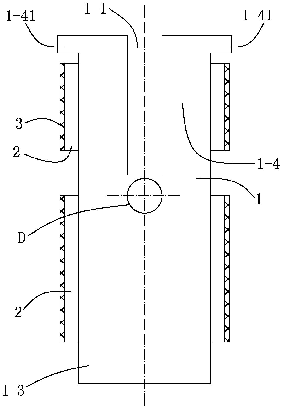
[0065] Embodiment 1, as figure 1 As shown, this embodiment further defines that: the cross-section of the opening groove 1-1 is a rectangle. It is processed into a regular rectangular slot with a straight bottom, easy to manufacture, guaranteed in size, and easy to miniaturize. Due to the symmetry of the structure, the acoustic node of the stator (the point that does not vibrate, has neither displacement nor corner) Clearly, a mounting hole D can be opened at this acoustic node to fix the stator, which does not affect the effects of longitudinal and bending vibration modes, and can be fixed reliably.

[0066] Optionally, the width W of the opening groove 1-1 is 0.2-10 mm, and the depth H is 0.5-10 mm.

[0067] Optionally, the stator is mainly composed of a rectangular thin-plate stator elastic body 1 and a piezoelectric ceramic sheet 2. The piezoelectric ceramic sheet is a rectangular sheet structure, and the rectangular parallelepiped driving foot 3 extended from the stator ...

Embodiment 2

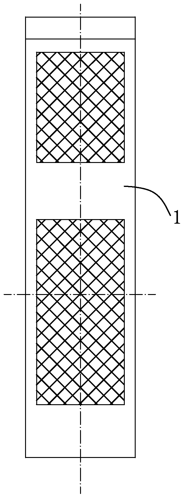
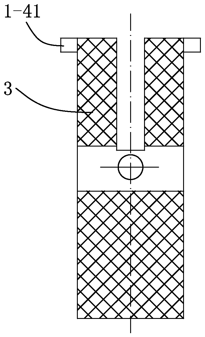
[0068] Embodiment 2, as image 3 and Figure 4 As shown, the body of the piezoelectric ceramic material stator in this embodiment is a cuboid, and it is further defined that the electrode layer 3 is sprayed on the two wide sides of the entire piezoelectric ceramic material stator in the length direction, so as to facilitate the polarization of the piezoelectric ceramic material in the thickness direction. Excitation of the material stator. Such as Figure 5 As shown, this embodiment further defines that the electrode layer 3 is sprayed on the two thick sides of the piezoelectric ceramic material stator in the length direction, so as to facilitate the excitation of the piezoelectric ceramic material stator polarized in the width direction.

Embodiment 3

[0069] Embodiment 3, this embodiment 3 is further defined in embodiment 1 and / or embodiment 2: the bottom corner of the open groove 1-1 is vertically opened with axisymmetric narrow groove 1- 2. The combined design of open slots and narrow slots has a better effect on adjusting the degeneracy of the local second-order bending vibration modes of the two driving legs of the stator and the first-order longitudinal vibration mode of the stator as a whole. Figure 6 Given the narrow slots on the stator elastic body 1, the body of the whole piezoelectric ceramic material stator in embodiment 2 has narrow slots and Figure 6 Same, omitted and not drawn.

[0070] The size combination of the open slot 1-1 and the narrow slot 1-2 degenerates (same or close to) the frequency of the bending vibration and the longitudinal vibration, and can obtain a better effect of driving the elliptical motion of the foot. Optionally, the width K of the narrow groove 1-2 is 0.1-1 mm, and the depth L is...


PUM


Abstract

The invention discloses a linear ultrasonic motor stator and an electric excitation method thereof. The stator comprises a stator elastic body and piezoelectric ceramic pieces, wherein an open slot isformed in the stator elastic body along the length direction, and the stator elastic body is divided into a driving body and two symmetrical driving legs by the open slot; the piezoelectric ceramic pieces in axial symmetry are attached to the two opposite outer side surfaces of the two driving legs, and driving feet extending outwards are arranged at the upper ends of the two driving legs respectively; and the piezoelectric ceramic pieces are coated with an electrode layer. The electric excitation method comprises the steps of 1) bonding the piezoelectric ceramic pieces; 2) preparing electrifying electrodes; and 3) simultaneously exciting local second-order bending vibration of the driving legs and overall first-order longitudinal vibration of the stator twice by using two paths of same-frequency sinusoidal voltage signals, and finally realizing forward and reverse movement of a driving rotor. According to the invention, the local second-order bending vibration of the two driving legsof the stator and overall first-order longitudinal vibration of the stator are combined and degenerate, and elliptical vibration of the driving feet is achieved.

Description

technical field [0001] The present invention relates to an ultrasonic motor and its electric excitation method, more specifically, to a linear ultrasonic motor stator and its electric excitation method. Background technique [0002] Ultrasonic motors use the inverse piezoelectric effect of piezoelectric materials to convert electrical energy into vibration energy of the stator, and excite elliptical or oblique arc vibrations at the driving end of the stator, and then convert them into rotation or straight lines of moving parts through contact friction. sports. Compared with traditional electromagnetic motors, ultrasonic motors have many unique advantages such as low-speed high-power output, quiet and noiseless operation, flexible design, compact structure, high energy density, and easy miniaturization. [0003] The stator is the core component of the ultrasonic motor. For a linear ultrasonic motor, the stator structure is mainly flat, and there are also a few slender cylind...

Claims


Application Information

Patent Timeline
Patent Type & Authority Applications(China)
IPC IPC(8): H02N2/04H02N2/14
CPCH02N2/04H02N2/14
Inventor 曲建俊曲华杰温众普
Owner HARBIN INST OF TECH
Why Eureka
Try Eureka