Eureka AIR delivers breakthrough ideas for toughest innovation challenges, trusted by R&D personnel around the world.

Wireless signal transfer system and wireless signal transfer method

A wireless signal and signal technology, applied in the transmission system, electrical components, etc., can solve the problems of blocking interference, shortening the transmission distance, and reducing the signal strength, so as to reduce signal interference, extend the transmission distance, and increase the transmission distance. Effect

Inactive Publication Date: 2020-07-28
NAWA ELECTRONICS SHANGHAI CO LTD
View PDF5 Cites 0 Cited by
  • Summary
  • Abstract
  • Description
  • Claims
  • Application Information

AI Technical Summary

Problems solved by technology

[0003] On the other hand, there are more and more types and models of wireless communication equipment, and there are more and more interferences. When wireless communication equipment is used, co-channel interference, blocking interference, spurious emission interference, and receiver sensitivity are unavoidable. High interference, etc., these interferences will lead to a decrease in signal transmission rate, an increase in bit error rate, dropped calls, and network instability
Even the higher the frequency of the wireless signal, the poorer its diffraction ability, and the transmission distance will be greatly shortened if encountering obstacles
[0004] Therefore, short-distance wireless signal transmission is subject to many problems of transmission distance and signal interference. For example, in remote mountainous areas, there are high mountains blocking it, and it is difficult for existing Wi-Fi LAN equipment to realize signal transmission.
In industrial production workshops in complex environments, long-distance data communication needs to be transmitted while avoiding interference of signals of the same frequency to prevent signal blocking, and the anti-interference ability of existing wireless communication equipment is insufficient
For another example, in an environment with complex terrain or obstacles, due to the high operating frequency of the wireless signal transmission equipment in the prior art, obstacles have a great influence on the wireless signal, resulting in the transmission of the wireless signal transmission equipment in the prior art The signal strength is reduced, and the signal transmission distance is reduced

Method used


Image

  • Wireless signal transfer system and wireless signal transfer method
  • Wireless signal transfer system and wireless signal transfer method
  • Wireless signal transfer system and wireless signal transfer method

Examples


Embodiment Construction

[0041] The following description serves to disclose the present invention to enable those skilled in the art to carry out the present invention. The preferred embodiments described below are only examples, and those skilled in the art can devise other obvious variations. The basic principles of the present invention defined in the following description can be applied to other embodiments, variations, improvements, equivalents and other technical solutions without departing from the spirit and scope of the present invention.

[0042] It can be understood that the term "a" should be understood as "at least one" or "one or more", that is, in one embodiment, the number of an element can be one, while in another embodiment, the number of the element The quantity can be multiple, and the term "a" cannot be understood as a limitation on the quantity.

[0043] With reference to the accompanying drawings of the description of the present invention Figure 1 to Figure 5B As shown, a w...


PUM


Abstract

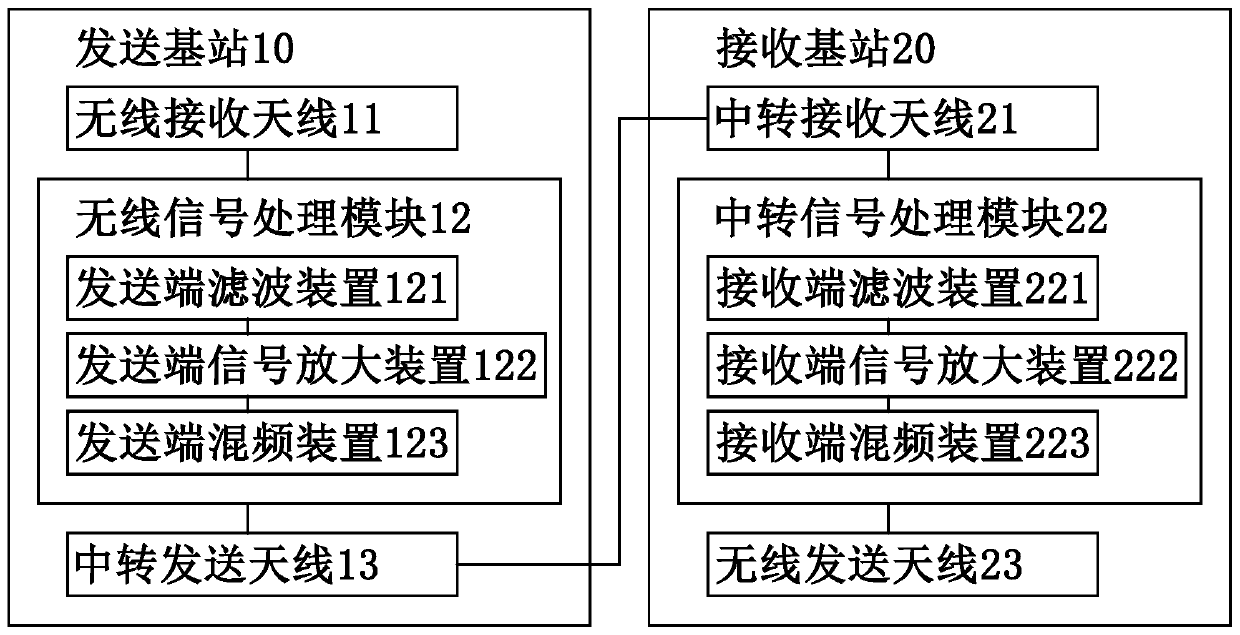
The invention provides a wireless signal transfer system and a wireless signal transfer method. The wireless signal transfer system comprises at least one sending base station and at least one receiving base station, wherein the at least one sending base station converts a wireless transmission signal into a transfer signal; wherein the at least one sending base station transmit the transfer signal to the outside, the frequency f0 of the wireless transmission signal is greater than the frequency f1 of the transfer signal, and the at least one receiving base station receive the transfer signaland converts the transfer signal into the wireless transmission signal with the frequency f0.

Description

technical field [0001] The invention relates to the field of wireless signal transmission, in particular to a wireless signal transfer system and a wireless signal transfer method. Background technique [0002] With the development of wireless network technology, wireless signal transmission has become an indispensable communication method in many application fields, such as Zig-Bee, Bluetooth (Bluetooth), wireless broadband (Wi-Fi), ultra-wideband (UWB) and near field Communication (NFC), etc. At present, Wi-Fi LAN is widely used in enterprises, office places, public places and many industries. However, according to the IEEE802.11 standard, WIFI is partially limited, and the transmission distance range is relatively small. The maximum distance covered by a general wireless router is usually 300 meters. about. [0003] On the other hand, there are more and more types and models of wireless communication equipment, and there are more and more interferences. When wireless co...

Claims


Application Information

Patent Timeline
Patent Type & Authority Applications(China)
IPC IPC(8): H04B1/04H04B1/10H04B1/12H04B1/16
CPCH04B1/04H04B1/10H04B1/12H04B1/16H04B2001/0408H04B2001/0491
Inventor 黄成林李建林
Owner NAWA ELECTRONICS SHANGHAI CO LTD
Why Eureka
Eureka Blog
Learn More