
Nano-photonics reflector for LED emitters

A reflector, LED device technology, applied in nano-optics, nanotechnology, nanotechnology, etc., can solve problems such as limiting performance gain

Pending Publication Date: 2020-07-28
LUMILEDS
View PDF7 Cites 1 Cited by
  • Summary
  • Abstract
  • Description
  • Claims
  • Application Information

AI Technical Summary

Problems solved by technology

However, practical DBR designs employ layers with limiting index contrast, which ultimately limits performance gain

Method used


Image

  • Nano-photonics reflector for LED emitters
  • Nano-photonics reflector for LED emitters
  • Nano-photonics reflector for LED emitters

Examples


Embodiment Construction

[0020] In the following description, numerous specific details are set forth, such as specific structures, components, materials, dimensions, process steps and techniques, in order to provide a thorough understanding of the present embodiments. However, it will be understood by those of ordinary skill in the art that these embodiments may be practiced without these specific details. In other instances, well-known structures or process steps have not been described in detail in order to avoid obscuring the embodiments. It will be understood that when an element such as a layer, region or substrate is referred to as being “on” or “over” another element, it can be directly on the other element or intervening elements may also be present. In contrast, when an element is referred to as being "directly on" or "directly on" another element, there are no intervening elements present. It will also be understood that when an element is referred to as being "under," "under" or "under" a...


PUM


Abstract

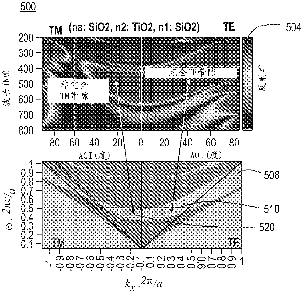
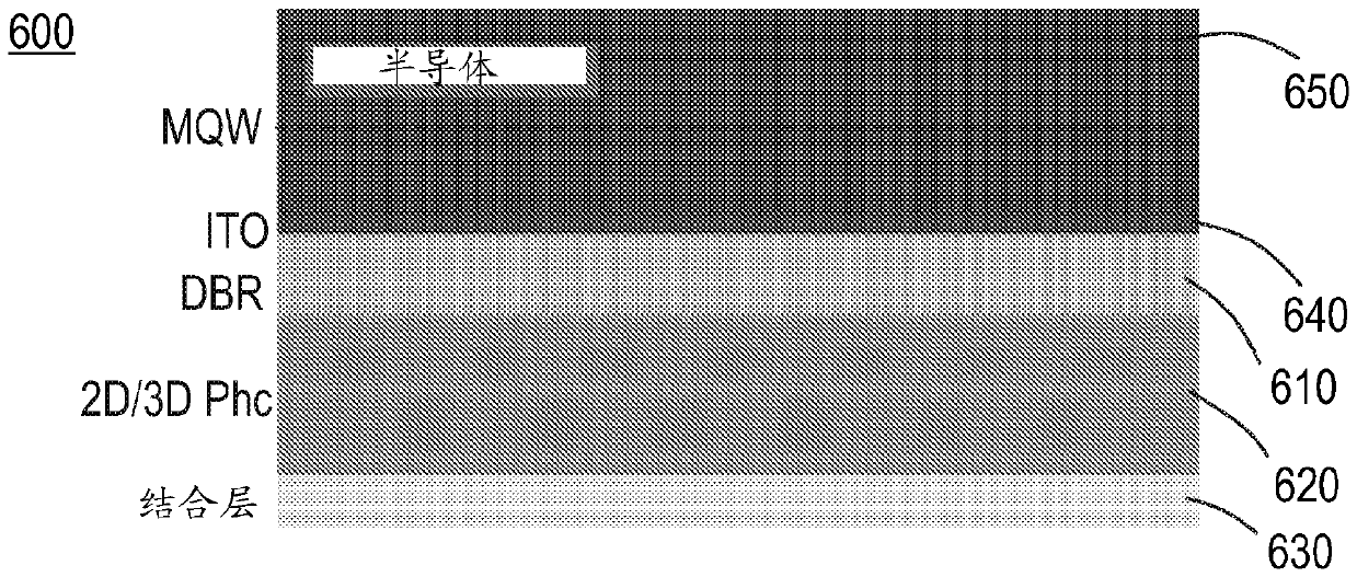
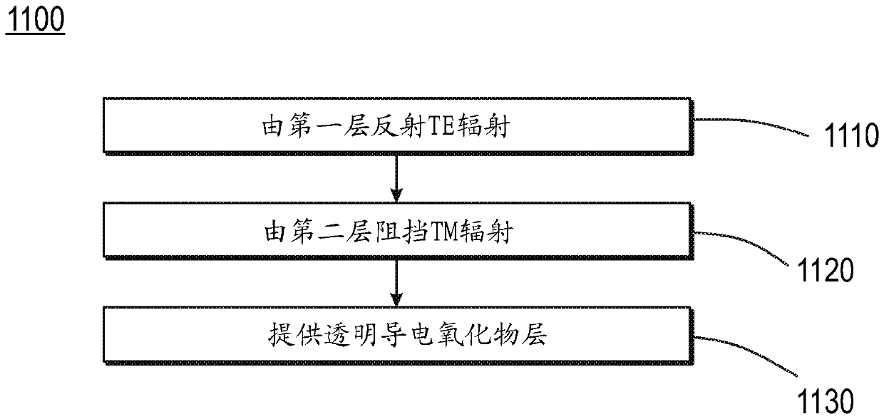
A system, method and device for use as a reflector for a light emitting diode (LED) are disclosed. The system, method and device include a first layer designed to reflect transverse-electric (TE) radiation emitted by the LED, a second layer designed to block transverse-magnetic (TM) radiation emitted from the LED, and a plurality of ITO layers designed to operate as a transparent conducting oxidelayer. The first layer may be a one-dimension (1D) distributed Bragg reflective (DBR) layer. The second layer may be a two-dimension (2D) photonic crystal (PhC), a three-dimension (3D) PhC, and / or a hyperbolic metamaterial (HMM). The 2D PhC may include horizontal cylinder bars, vertical cylinder bars, or both. The system, method and device may include a bottom metal reflector that may be Ag free and may act as a bonding layer.

Description

[0001] Cross References to Related Applications [0002] This application requires the title " Nanophotonic reflectors for LED emitters benefit of U.S. Provisional Application No. 62 / 573,382, filed October 17, 2017, and U.S. Nonprovisional Application No. 16 / 160,713, filed October 15, 2018, and to the benefit of European Patent Application No. 18152921.5, both of which are incorporated by reference as if fully set forth. technical field [0003] The present invention relates to a nanophotonic reflector for a light-emitting diode (LED) emitter, and more particularly, to a reflector structure that improves the constrained reflectivity of a distributed Bragg reflector (DBR) to Completely blocks incoming light. Background technique [0004] The reflectivity of typical composite mirror architectures is limited by the refractive index contrast between the semiconductor and the rather thick oxide layers separating the lossy metal reflectors. Light incident at angles outside the ...

Claims


Application Information

Patent Timeline
IPC IPC(8): H01L33/46
CPCH01L33/46H01L33/32H01L33/42H01L33/30B82Y20/00H01L2933/0083G02B5/3041G02B1/005G02B27/283H01L33/10G02B6/1225G02B5/00H01L33/405
Inventor T.罗佩斯V.A.塔马
Owner LUMILEDS
Learn More