
A workpiece rotating device for laser engraving based on the field of laser and optical communication

A laser engraving and rotating device technology, which is applied in laser welding equipment, manufacturing tools, metal processing equipment, etc., can solve problems such as low processing precision, inability to realize rapid adjustment and automatic locking of the adjustment structure, and inability to ensure uniform tightening force, etc. , to achieve the effect of improving the regulation efficiency

Active Publication Date: 2021-11-05
河南百合特种光学研究院有限公司
View PDF10 Cites 0 Cited by
  • Summary
  • Abstract
  • Description
  • Claims
  • Application Information

AI Technical Summary

Problems solved by technology

[0007] In order to solve the above-mentioned technical problems, the present invention provides a workpiece rotating device for laser engraving based on the field of laser and optical communication, to solve the existing problem that the machining accuracy is low, and most of the existing devices use screw threads when fixing. The way of tightening is fixed, and this kind of fixing method can not guarantee the uniformity of tightening force every time when fixing, thus just can not realize the precision of engraving of blank of the same type; Poor, if a hard object falls on the sliding track during use, it will easily cause the sliding track to deform, and then cause the sliding track to be unable to use normally; finally, the adjustment structure of the existing device cannot realize quick adjustment and automatic locking after adjustment The problem

Method used


Image

  • A workpiece rotating device for laser engraving based on the field of laser and optical communication
  • A workpiece rotating device for laser engraving based on the field of laser and optical communication
  • A workpiece rotating device for laser engraving based on the field of laser and optical communication

Examples


Embodiment

[0035] as attached figure 1 to attach Figure 9 Shown:

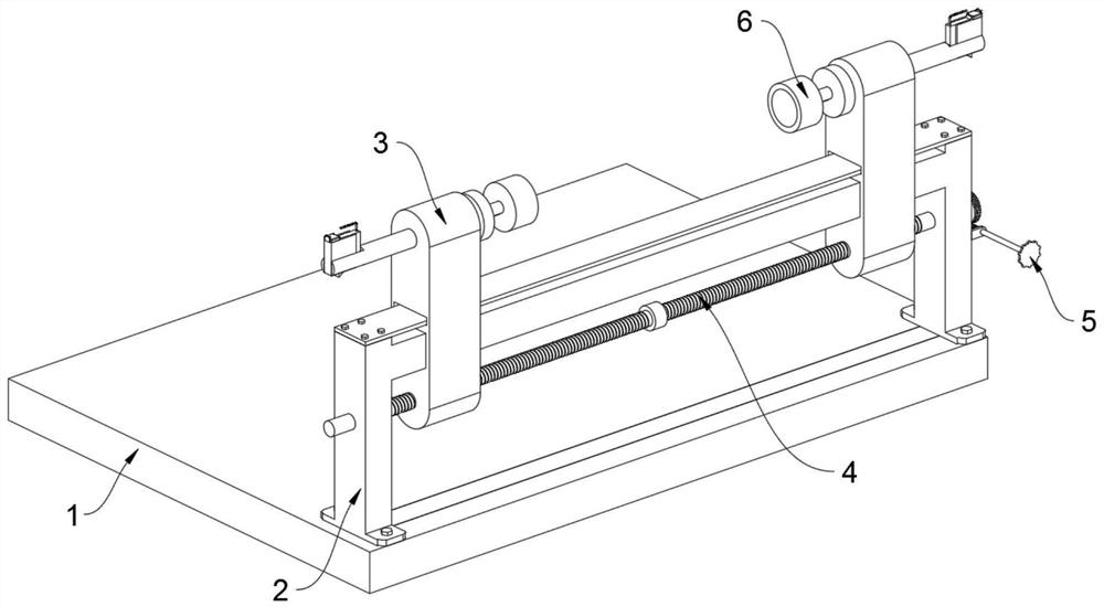
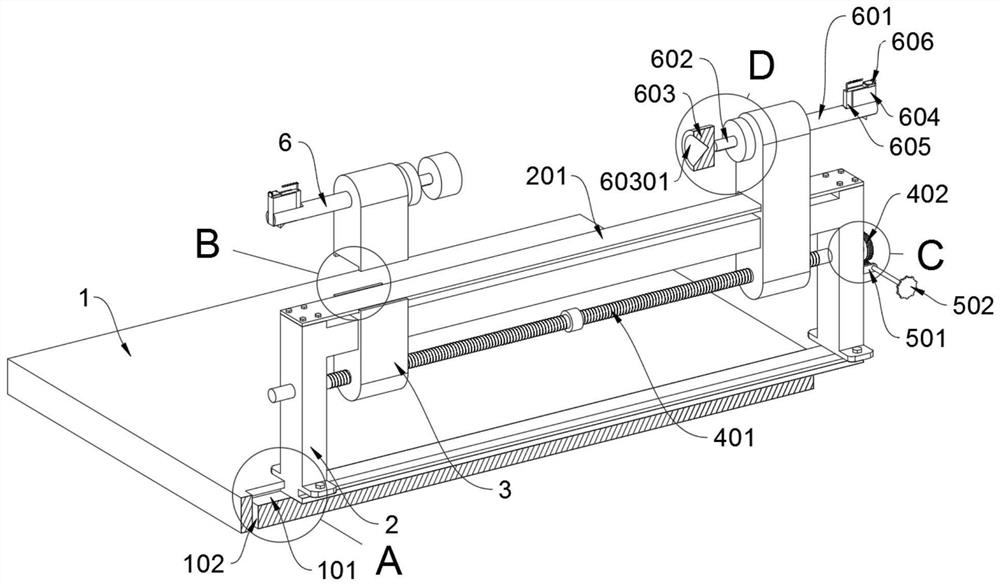
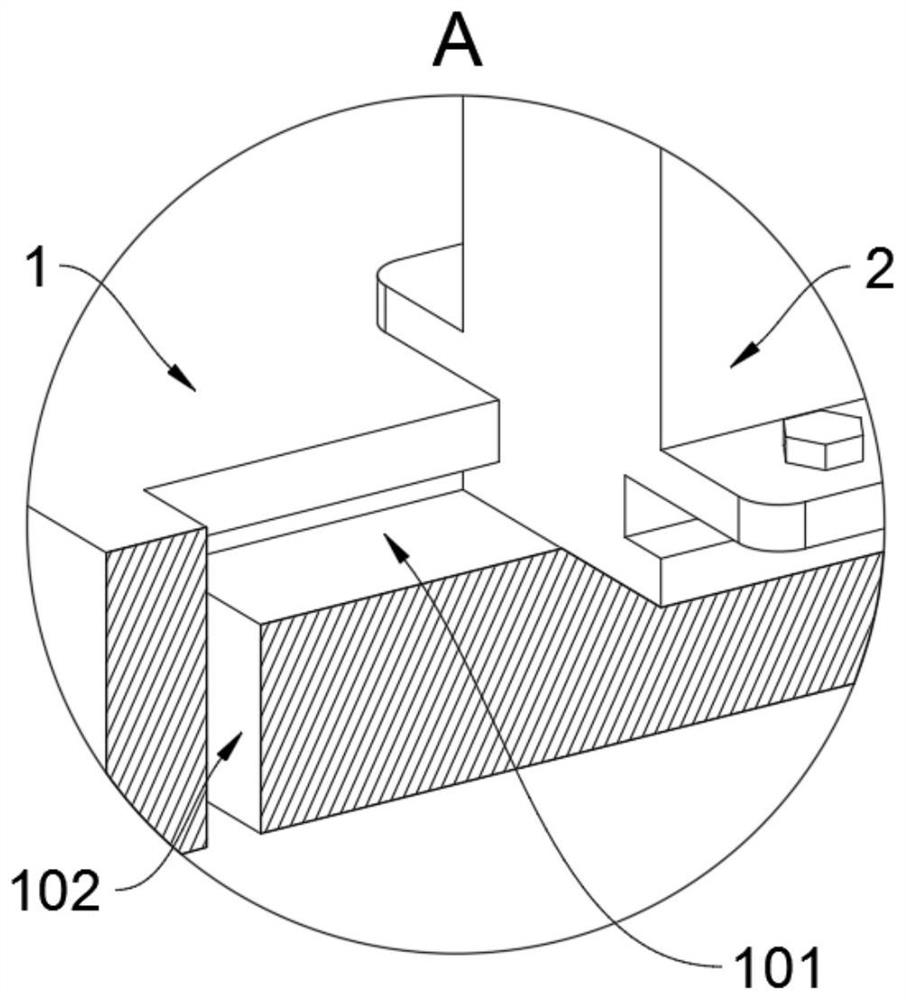
[0036] The invention provides a workpiece rotating device for laser engraving based on the field of laser and optical communication, which includes a base 1; a sliding seat 2 is fixedly connected to the base 1, and two adjustment seats 3 are slidably connected to the sliding seat 2, and each A fixed structure 6 is rotatably connected to each adjustment seat 3; refer to as figure 2 , the sliding seat 2 is a concave frame structure, and the top surface of the sliding seat 2 is fixedly connected with a baffle 201 by bolts; the adjusting seat 3 includes a rectangular hole A301, and the adjusting seat 3 is provided with a rectangular hole A301, and the adjusting seat 3 Sliding connection with the sliding seat 2 through the rectangular hole A301; the top beam part of the sliding seat 2 is a sliding track, and the baffle plate 201 forms the protective structure of the beam part of the sliding seat 2. The setting of the baffl...


PUM


Abstract

The invention provides a workpiece rotating device for laser engraving based on the field of laser and optical communication, which relates to the field of workpiece rotating device, and solves the problem that screw tightening cannot ensure the uniform tightening force, so that the same type of blank carving accuracy cannot be achieved; During use, if a hard object falls on the sliding track, it will easily cause the sliding track to deform, and then cause the sliding track to be unable to use normally; the adjustment structure of the existing device cannot realize the problem of quick adjustment and automatic locking after adjustment. A workpiece rotating device for laser engraving based on the field of laser and optical communication, comprising a base; a sliding seat is fixedly connected to the base. When the blank needs to be replaced, the replacement of the blank can be realized through the disassembly and assembly of the fixed block, and compared with the adjustment of the adjustment seat and the replacement of the blank by adjusting the adjustment rod, the structure of this place can achieve the same clamping degree after replacement. , and then also realized the precision of the same batch of blank parts processing.

Description

technical field [0001] The invention belongs to the technical field of workpiece rotating devices, and more specifically relates to a workpiece rotating device for laser engraving based on the field of laser and optical communication. Background technique [0002] Laser engraving is based on numerical control technology, and laser is the processing medium. The physical denaturation of the instant melting and gasification of the processed material under laser irradiation achieves the purpose of processing. [0003] For example, the application number: CN201820814129.X, the utility model provides a workpiece rotating device for laser engraving, and relates to the field of workpiece rotating devices. The workpiece rotating device for laser engraving includes a mounting seat, a limiting groove is opened on the upper surface of the mounting seat, a flashboard is overlapped with the inner bottom wall of the limiting groove, and the rotating device body is welded on the top of the...

Claims


Application Information

Patent Timeline
Patent Type & Authority Patents(China)
IPC IPC(8): B23K26/362B23K26/70
CPCB23K26/362B23K26/702
Inventor 孔慧君李静闵茹
Owner 河南百合特种光学研究院有限公司
Learn More