
Internal combustion engine crankshaft finish machining process

A technology for internal combustion engines and crankshafts, which is applied to crankshafts, metal processing equipment, shafts, etc., and can solve problems such as ineffective finishing of crankshafts, poor finishing effects of connecting journals, and the fact that the main journal and connecting journals are not located on the same plane.

Inactive Publication Date: 2020-07-31
王鹏
View PDF0 Cites 2 Cited by
  • Summary
  • Abstract
  • Description
  • Claims
  • Application Information

AI Technical Summary

Problems solved by technology

[0003] In the processing technology of the crankshaft, it is often necessary to finish the crankshaft. In the process of grinding the outer surface of the crankshaft journal, there are often the following problems: 1. Since the crankshaft contains the main journal and the connecting journal, the crankshaft rotates , the movement trajectory of the connecting journal is consistent with the cam, which leads to the fact that the main journal and the connecting journal are not located on the same plane, and the movement trajectory of the connecting journal is not located on the same plane, which makes the grinding device unable to effectively stick to the main journal and Connect the journal, so that the finishing effect on the crankshaft is not obvious; 2. When facing crankshafts of different specifications, it is necessary to adjust the grinding block that is fed with the connecting journal, which leads to the fact that the excessively adjusted grinding block cannot fit the connection The movement track of the journal makes the finishing effect of the connecting journal not good

Method used


Image

  • Internal combustion engine crankshaft finish machining process
  • Internal combustion engine crankshaft finish machining process
  • Internal combustion engine crankshaft finish machining process

Examples


Embodiment Construction

[0028] The embodiments of the present invention will be described in detail below with reference to the accompanying drawings, but the present invention can be implemented in many different ways defined and covered by the claims.

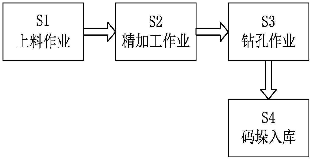
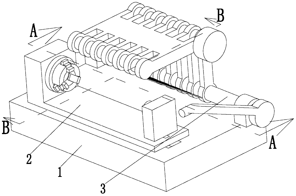
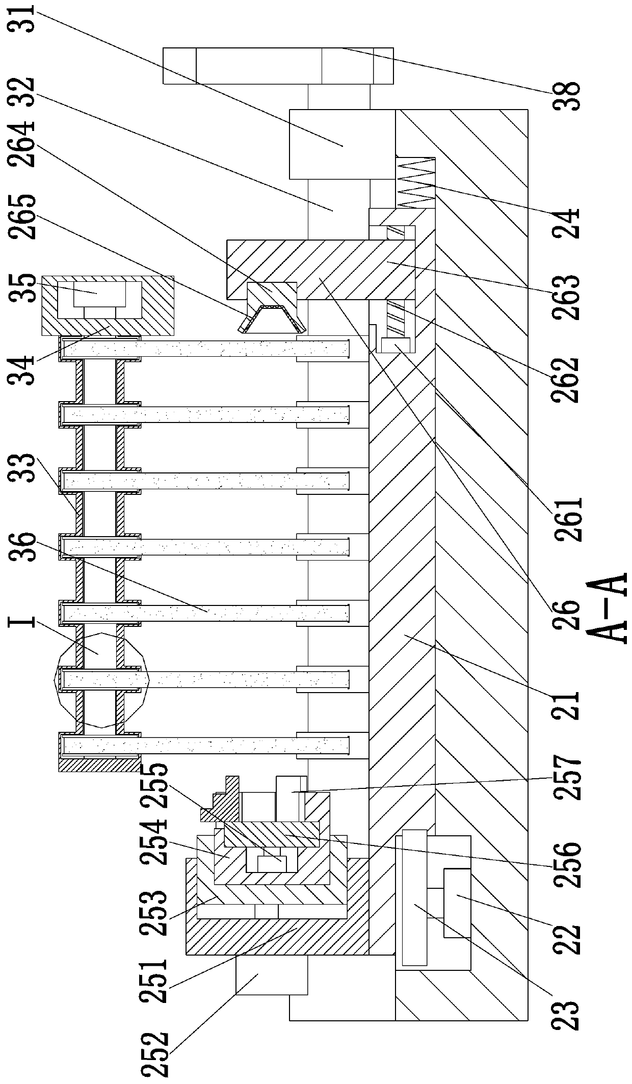
[0029] Such as Figure 1 to Figure 6 Shown, a kind of crankshaft finishing process of internal combustion engine, it has used a kind of crankshaft finishing device, and this crankshaft finishing device comprises base 1, clamping unit 2 and grinding unit 3, adopts above-mentioned crankshaft finishing device to the finishing of crankshaft The method also includes the steps of:

[0030] S1. Loading operation: the crankshaft is fixed and clamped by the clamping unit 2;

[0031] S2. Finishing operation: use the grinding unit 3 to perform finishing treatment on the surface of the crankshaft fixed in step S1;

[0032] S3. Drilling operation: provide an oil hole to the crankshaft journal after finishing in step S2 by manual or mechanical assistance;

[0...


PUM


Abstract

The invention relates to an internal combustion engine crankshaft finish machining process. In the internal combustion engine crankshaft finish machining process, a crankshaft finish machining deviceis used, the crankshaft finish machining device comprises a base, a clamping unit and a polishing unit, the front side of the upper end of the base is provided with the clamping unit, and the rear side of the upper end of the base is provided with the polishing unit. According to the internal combustion engine crankshaft finish machining process, by adopting a belt polishing mode, the effect of simultaneously polishing a crankshaft main journal and a connecting journal through one structure can be achieved by utilizing the elasticity of a belt, and the problem that a polishing device cannot beeffectively attached to the main journal and the connecting journal at the same time and then the finish machining effect on the crankshaft connecting journal is not obvious is solved; and through left-right reciprocating shaking of the rotating crankshaft, the polishing belt can completely polish the outer surface of the crankshaft journal, and the situation that the polishing belt cannot completely cover the outer surface of the crankshaft journal is prevented.

Description

technical field [0001] The invention relates to the technical field of engine processing, in particular to a finishing process for an internal combustion engine crankshaft. Background technique [0002] The crankshaft is the most important component in the engine. It bears the force transmitted by the connecting rod and converts it into torque through the crankshaft output and drives other accessories on the engine to work. The crankshaft is subjected to the joint action of the centrifugal force of the rotating mass, the periodically changing gas inertial force and the reciprocating inertial force, so that the crankshaft is subjected to the bending torsional load. Therefore, the crankshaft is required to have sufficient strength and rigidity, and the surface of the journal needs to be wear-resistant, work evenly, and have good balance. Usually we refer to the engine speed as the crankshaft speed. [0003] In the processing technology of the crankshaft, it is often necessa...

Claims


Application Information

Patent Timeline
IPC IPC(8): B24B1/00B24B21/02B24B21/18B24B41/06B23P15/00
CPCB23P15/00B23P2700/07B24B1/00B24B21/02B24B21/18B24B41/06
Inventor 王鹏宛磊
Owner 王鹏
Learn More