
Membrane electrode packaging structure and packaging method

A packaging structure and packaging method technology, applied in the direction of circuits, fuel cells, electrical components, etc., can solve problems such as high difficulty in quality control, lower production efficiency, and affect performance, so as to save frame materials and adhesive materials, and reduce leakage Possibility of air leakage and the effect of reducing the problem of air leakage

Pending Publication Date: 2020-07-31
SINOHYKEY TECH CO LTD
View PDF0 Cites 1 Cited by
  • Summary
  • Abstract
  • Description
  • Claims
  • Application Information

AI Technical Summary

Problems solved by technology

[0004] (1) High cost:
[0005] Because it is a double-layer frame structure, the amount of frame materials and adhesives is large, and the cost is high for mass production, especially because the working environment of fuel cells involves high and low humidity cycles, high and low temperature cycles, and strong chemical corrosion. Harsh conditions such as (free radicals) require the use of special-purpose adhesives. The development and production costs of this type of adhesive are relatively high, so if the amount of adhesive used is large, the cost will be high
[0006] (2) High difficulty in quality control:
[0007] ① There may be unevenness when pre-coating the glue on the frame, for example, there are defect points such as no glue or less glue in some areas, which can easily make the gas on the side of the catalyst coating film break through the sealing structure formed by the adhesive layer Leakage to the other side of the catalyst coated membrane causing outgassing and affecting performance
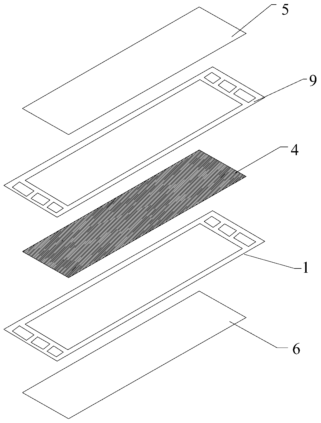
[0008] ② if figure 2 When the two-layer frame 1, 9 and the catalyst coating film 4 are pressed together after pre-coating, there may be uneven pressing force, which will cause defects, such as bubbles 10 in the first adhesive 3, It is also possible that the gas on one side of the catalyst-coated membrane 4 leaks to the other side of the catalyst-coated membrane through the air bubbles 10 in the first adhesive 3, resulting in air leakage.
Although the problem of air bubbles and other defects can be alleviated to a certain extent by improving the pressing methods, such as using rolling instead of flat pressing, and pre-vacuumizing, it is still difficult to completely solve the problem of air bubbles, and pre-vacuumizing also consumes time and reduce production efficiency
[0009] ③ After pre-coating, when the two-layer frame 1, 9 and the catalyst coating film 4 are pressed together, deformation and displacement are prone to occur, so that precise alignment cannot be achieved

Method used


Image

  • Membrane electrode packaging structure and packaging method
  • Membrane electrode packaging structure and packaging method
  • Membrane electrode packaging structure and packaging method

Examples


Embodiment Construction

[0034] The specific embodiments described here are only used to explain the present invention, not to limit the present invention.

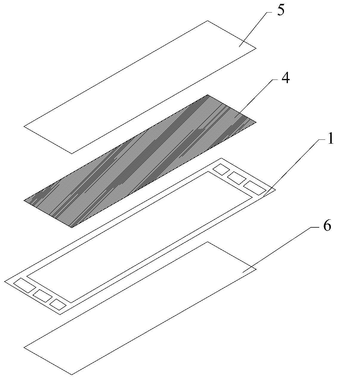
[0035] Such as Figure 5 , the membrane electrode encapsulation method comprises the following steps:

[0036] ① Using only one frame 1, surface plasma etching or laser etching is performed on the top surface of the frame 1 to construct a depression 2, and the area surrounded by the inner side wall 21 of the depression 2 (such as Figure 6 The area surrounded by dotted lines) is the same shape and size as the catalyst coating film 4, and the thickness value of the inner side wall 21 at the depression 2 is equal to the thickness value of the catalyst coating film 4;

[0037] ② Coating a layer of first adhesive 3 with a thickness of 3 to 20 microns on the bottom wall 22 of the depression 2, and the first adhesive 3 is in contact with the inner side wall 21 of the depression 2;

[0038] ③ Put the catalyst coating film 4 into the area surrounded by...


PUM


Abstract

The invention relates to the field of fuel cells, in particular to a membrane electrode packaging structure and a packaging method. The membrane electrode packaging structure comprises a top surface gas diffusion layer and a bottom surface gas diffusion layer, a frame and a catalyst coating film which are mutually stacked are clamped between the two gas diffusion layers, the catalyst coating filmis bonded and fixed on the top surface of the frame, only one frame is arranged, the part, bonded with the catalyst coating film, of the top surface of the frame is concave, the catalyst coating filmis bonded on the bottom wall of the concave part, and the inner side wall of the concave part blocks the periphery of the catalyst coating film. The packaging structure can reduce the production costand reduce the air leakage risk of the sealing area.

Description

technical field [0001] The invention relates to the field of fuel cells, in particular to a membrane electrode packaging structure and packaging method. Background technique [0002] Such as figure 1 , the current mainstream packaging method for membrane electrodes is as follows: firstly, the anode catalyst layer and the cathode catalyst layer are respectively coated on both ends of the proton exchange membrane to prepare a catalyst-coated membrane 4 (CCM) with a three-layer structure; then the catalyst is coated The edges of the membrane 4 and the edges of the two frames 1 and 9 are bonded and sealed with an adhesive to form a five-layer assembly; the last two layers of gas diffusion layers 5 and 6 are respectively bonded to the frame by an adhesive to form a seven-layer assembly the membrane electrode. [0003] Although the above double-layer frame membrane electrodes can meet the basic sealing requirements, they have the following two main disadvantages in large-scale m...

Claims


Application Information

Patent Timeline
Patent Type & Authority Applications(China)
IPC IPC(8): H01M8/0273H01M8/1004
CPCH01M8/0273H01M8/1004Y02E60/50Y02P70/50
Inventor 邹渝泉吴力杰唐军柯叶思宇杨云松孙宁
Owner SINOHYKEY TECH CO LTD
Learn More