Hot end seat, thermoelectric power generation system, liquid reactor, operation method of liquid reactor, and application of thermoelectric power generation system

A technology of thermoelectric power generation and thermoelectric power generation sheets, which is applied in the direction of generators/motors, electrical components, indirect heat exchangers, etc., which can solve the problem that the heat of heat pipes cannot be effectively used, reduce the efficiency of thermoelectric power generation, and cannot ensure effective heat dissipation at the condensing end of heat pipes, etc. problems, to avoid local hot spots, improve efficiency, and improve heat utilization

Active Publication Date: 2020-07-31
SHANGHAI INST OF APPLIED PHYSICS - CHINESE ACAD OF SCI
View PDF8 Cites 0 Cited by
  • Summary
  • Abstract
  • Description
  • Claims
  • Application Information

AI Technical Summary

Problems solved by technology

[0005] The technical problem to be solved by the present invention is to overcome the heat pipe molten salt reactor temperature difference power generation system in the prior art. Due to the dense arrangement of heat pipes and the limitation of the arrangement mode, it is impossible to ensure effective heat dissipation at the condensing end of the heat pipes, which will cause The heat of the heat pipe in the central area cannot be effectively used, which will reduce the defect of thermoelectric power generation efficiency, and provide a hot end seat, thermoelectric power generation system, liquid stack and its operation method and application

Method used


Image

  • Hot end seat, thermoelectric power generation system, liquid reactor, operation method of liquid reactor, and application of thermoelectric power generation system
  • Hot end seat, thermoelectric power generation system, liquid reactor, operation method of liquid reactor, and application of thermoelectric power generation system
  • Hot end seat, thermoelectric power generation system, liquid reactor, operation method of liquid reactor, and application of thermoelectric power generation system

Examples


Embodiment 1

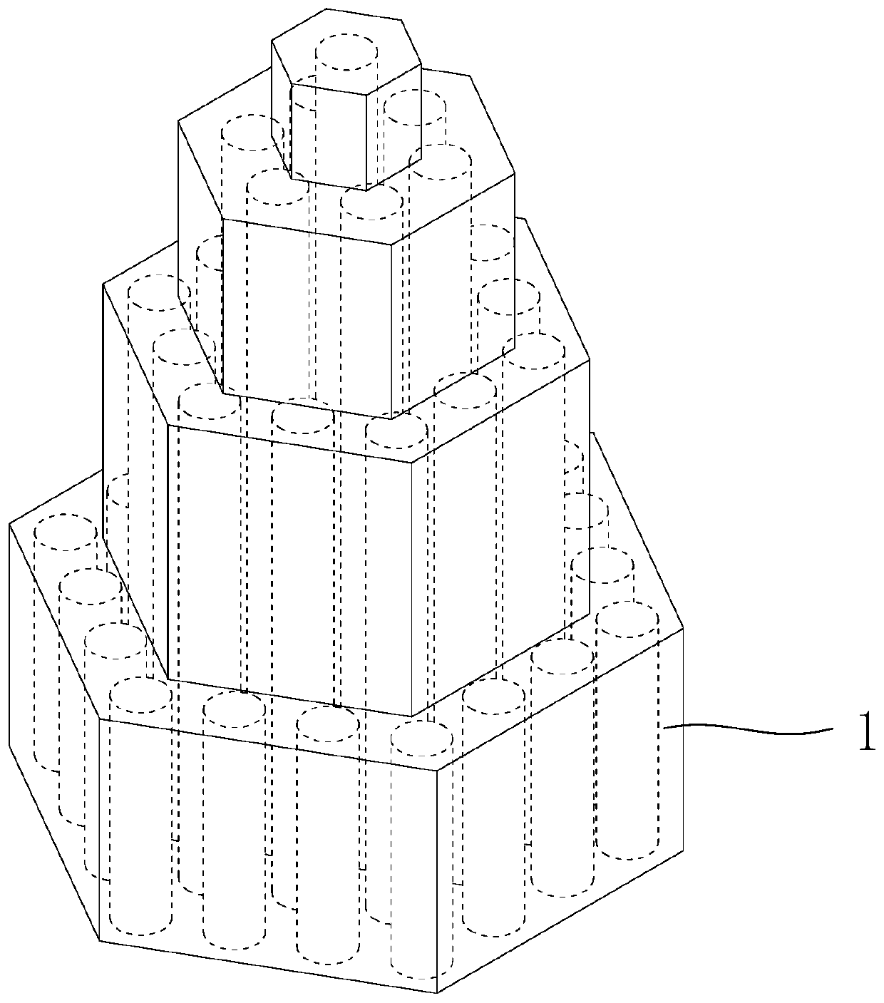
[0069] (1) Hot End Block

[0070] like figure 1 The hot end block shown is used to cooperate with the condensing end of the core heat pipe in the liquid stack;

[0071] The position of the top of the condensing end of the core heat pipe rises sequentially from outside to inside; and according to the height of the top of the condensing end of the core heat pipe, the condensing end of the core heat pipe is divided into the first to the first N areas;

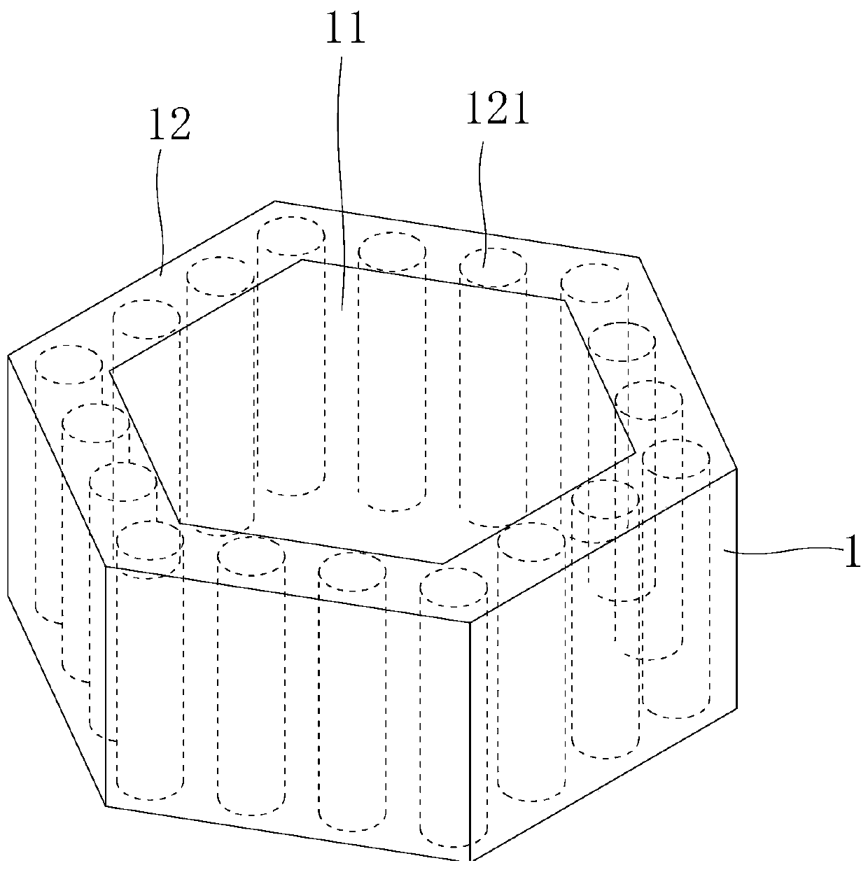
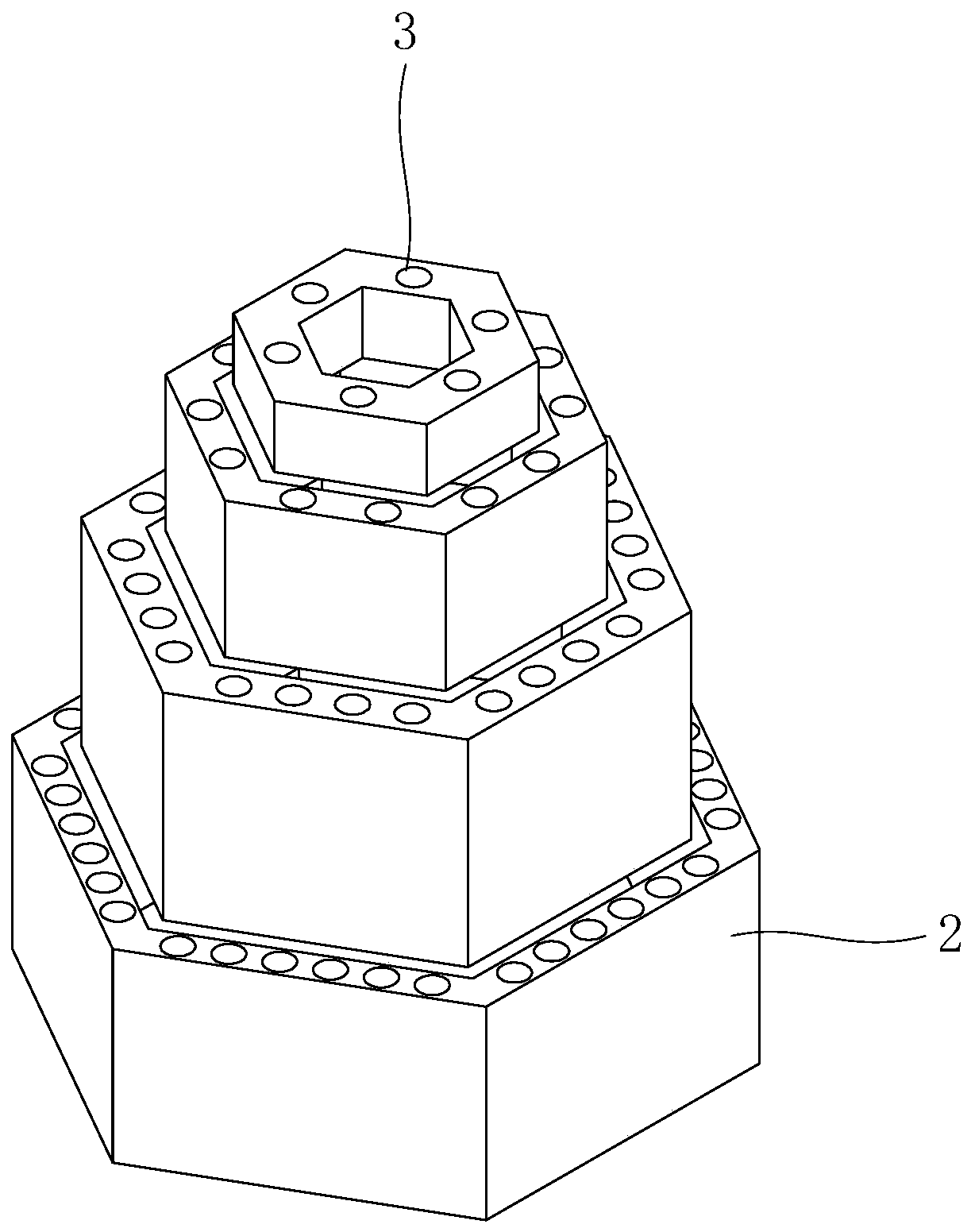
[0072] The hot end seat includes the first layer to the Nth layer of hot end sleeves from bottom to top, and the outer diameter of the hot end sleeve 1 becomes smaller from bottom to top. The structure of the first layer of hot end sleeves is shown in figure 2 ;

[0073] The hot end cover 1 of the hot end seat corresponds to the area of ​​the condensing end of the core heat pipe;

[0074] The hot end sleeve 1 has a central body 11 and an outer peripheral body 12 surrounding the central body 11; the central body 11 is used to ...


PUM


Abstract

The invention discloses a hot end seat, a thermoelectric power generation system, a liquid reactor, an operation method of the liquid reactor, and application of the thermoelectric power generation system. The hot end seat is used for being matched with the condensation ends of reactor core heat pipes in a liquid reactor, wherein the positions of the tops of the condensation ends of the reactor core heat pipes are sequentially increased from outside to inside, the condensation ends of the reactor core heat pipes are divided into the first to Nth areas from outside to inside, the hot end seat comprises hot end sleeves from the first layer to the Nth layer from bottom to top, the outer diameters of the hot end sleeves are decreased layer by layer from bottom to top, the hot end sleeve of thehot end seat corresponds to the area of the condensation end of the reactor core heat pipe, the hot end sleeve is provided with a center body and an outer edge body surrounding the center body, the center body is used for passing through the reactor core heat pipe in the areas corresponding to other layers above the layer, the outer edge body is provided with a reactor core heat pipe channel, andthe reactor core heat pipe channel is used for containing the condensation end of the reactor core heat pipe in the area corresponding to the layer. According to the hot end seat, heat of the reactorcore heat pipe can be smoothly brought out, so that local hot spots are avoided, and the heat utilization rate and the thermoelectric power generation efficiency are improved.

Description

technical field [0001] The invention relates to a hot end seat, a thermoelectric power generation system, a liquid stack and an operation method and application thereof. Background technique [0002] In the reactor system using heat pipes for core cooling, when one or more heat pipes in the core fail, the nuclear reaction heat of the failed heat pipe fuel assembly is exported to the core through the heat pipe in the center of the adjacent fuel assembly, thereby effectively avoiding a single point of heat transfer in the core Failure, therefore, has the advantage of being inherently redundant. Furthermore, the reactor system using heat pipes for core cooling has the advantages of easy start-up and no need for other auxiliary systems, so it has attracted special attention. In addition, since the heat pipe is directly inserted into the core and connected to the subsequent thermoelectric conversion system, the heat exchange between the core coolant and the external circuit is o...

Claims


Application Information

Patent Timeline
Patent Type & Authority Applications(China)
IPC IPC(8): H02N11/00F28D15/02
CPCF28D15/0275H02N11/002
Inventor 陈兴伟邹杨戴叶郭磊
Owner SHANGHAI INST OF APPLIED PHYSICS - CHINESE ACAD OF SCI
Why Eureka
Try Eureka