Valve

A valve seat and piston technology, applied in the field of valves, achieves simple manufacturing, large tolerance, weight and cost savings

Inactive Publication Date: 2020-07-31
CPT GRP GMBH
View PDF11 Cites 0 Cited by
  • Summary
  • Abstract
  • Description
  • Claims
  • Application Information

AI Technical Summary

Problems solved by technology

The disadvantage is that when opening the valve, the solenoid must generate a correspondingly high magnetic force in order to additionally resist the resultant force
Therefore, such valves require a large solenoid, which must be supplied with a corresponding current

Method used


Image

  • Valve
  • Valve
  • Valve

Examples


Embodiment Construction

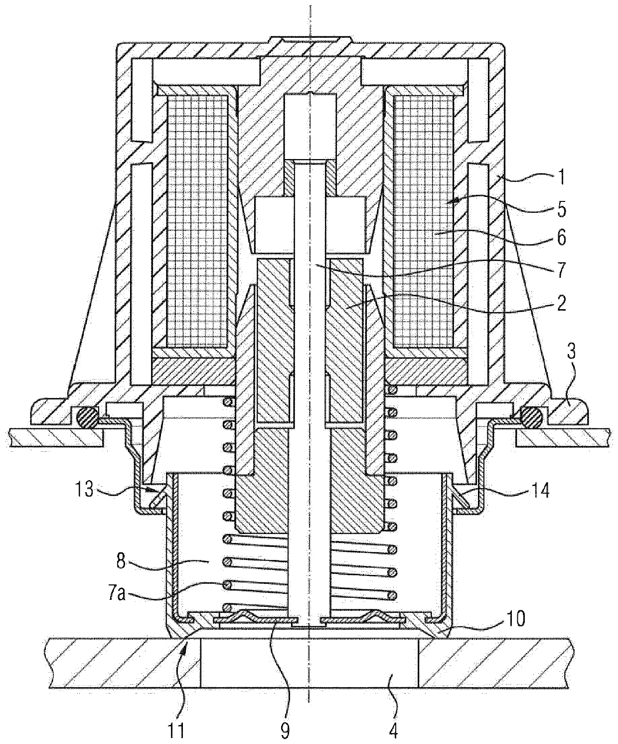
[0025] figure 1 The valve is shown, including the housing 1 . Furthermore, the housing 1 has an integral flange 3 , via which the housing 1 is flanged to a turbocharger (not shown) in the region of the bypass line 4 . A solenoid 5 with a coil 6 and a metal rod 7 is arranged in the housing 1 . The metal rod 7 is connected to a pot-shaped piston 8 which has a seal 10 on the circumference of its base 9 . In the closed position shown, the sealing structure 10 bears against the valve seat 11 in order to close the bypass line 4 so that no medium can flow from the line 4 into the line 12 . In this case, the spring 7 a pushes the piston 8 against the valve seat 11 . A further seal 13 with a sealing lip 14 is arranged at the open end of the piston 8 . If the solenoid 5 is energized, a magnetic force acts on the armature 2 , thereby moving the piston 8 in the direction of the housing 1 . The sealing lip 14 here seals the piston 8 relative to the housing 1 .

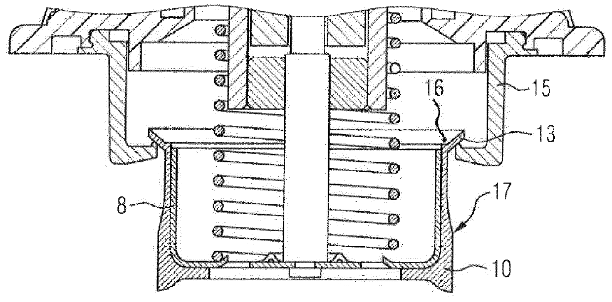
[0026] figure 2 The...


PUM


Abstract

The invention relates to a valve comprising a housing, a solenoid which is arranged in the housing, a pin which can be moved by the solenoid, a cup-shaped piston which is connected to the pin, a sealwhich is arranged in the base region of the piston and interacts with a valve seat, and a seal which is arranged in the region of the open end of the piston and seals the piston from the housing. Theseal (10) which interacts with the valve seat (11) has an outer diameter which approximately corresponds to the outer diameter of the seal (13) at the open end of the piston (8).

Description

technical field [0001] The invention relates to a valve comprising: a housing; a solenoid arranged in the housing; a rod movable by the solenoid; a pot-shaped piston connected to the rod; Seat cooperating sealing structure / seal; and a seal / seal or stop in the region of the open end of the piston. Background technique [0002] Such valves are used primarily as air steering valves on turbochargers in motor vehicles in order to open a bypass to the intake side during freewheeling and are therefore known. In order to prevent excessive braking of the turbocharger, but also to ensure a fast start-up, fast opening and closing of the valve is an important prerequisite. It is especially important when closing that an immediate closure is achieved by placing the piston on the valve seat. The valve seat is formed by the housing of the turbocharger, to which the valve is flanged. Furthermore, the axially movable piston must be sealed relative to the housing or its movement must be re...

Claims


Application Information

Patent Timeline
Patent Type & Authority Applications(China)
IPC IPC(8): F16K39/02F02B37/18F16K1/46F16K31/06
CPCF16K39/022F16K1/46F16K31/0655Y02T10/12F02B37/16F16K1/34F16K31/0651
Inventor R·博南诺
Owner CPT GRP GMBH
Why Eureka
Try Eureka