Electric kettle, and heating control circuit and heating control method for electric kettle

A technology for heating control circuit and control circuit board, which is applied in the direction of timing control ignition mechanism, heating device, water boiling appliance, etc., can solve the problem that the heating plate 11 cannot be used together, the fryer or melting machine is damaged, and cannot work normally, etc. problem, to achieve the effect of improving homogeneity, stable and reliable circuit, and avoiding substantial increase

Inactive Publication Date: 2020-08-04
BEAR ELECTRICAL APPLIANCE CO LTD +1
View PDF5 Cites 0 Cited by
  • Summary
  • Abstract
  • Description
  • Claims
  • Application Information

AI Technical Summary

Problems solved by technology

Therefore, the base 2 and the pot body 1 are used together one by one, and different pot bodies 1 may have different predetermined heating power P0. The heating plate 11 cannot be used in conjunction with the same base 2.
For example, there are actually two electric kettles: electric kettle A has a rated heating power of 500W, and electric kettle B has a rated heating power of 800W. Even if the body of electric kettle B can be placed on the base of electric kettle A, an overload phenomenon will occur , this is because the resistance value of the heating plate in electric kettle B is larger, the base of electric kettle A must greatly increase the heating current flowing through the heating plate in electric kettle B to make the heating power reach the rated heating power of 500W, overload will There are two serious consequences: one is that the rapidly increasing heating current may cause the fuse F1 to blow and fail to work normally; The heating power of the heating plate in B is much greater than its own rated heating power of 800W, and there is a risk of damage to the fryer or melter.

Method used


Image

  • Electric kettle, and heating control circuit and heating control method for electric kettle
  • Electric kettle, and heating control circuit and heating control method for electric kettle
  • Electric kettle, and heating control circuit and heating control method for electric kettle

Examples


Embodiment Construction

[0029] In order to further explain the technical means and functions adopted by this application to achieve the predetermined purpose, the specific implementation, structure, features and functions according to this application will be described in detail below in conjunction with the drawings and preferred embodiments. In the following description, different "one embodiment" or "embodiment" do not necessarily refer to the same embodiment. Furthermore, the particular features, structures, or characteristics of one or more embodiments may be combined in any suitable manner.

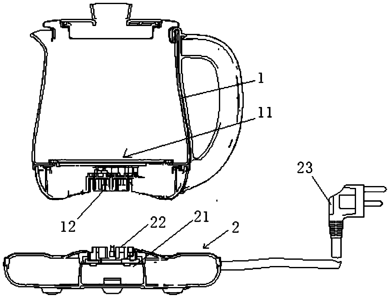
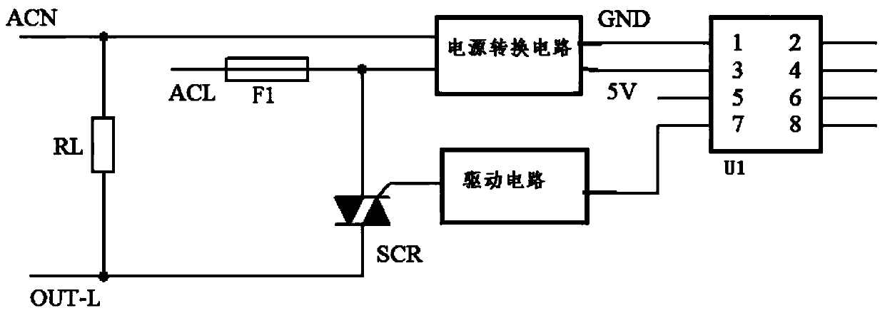
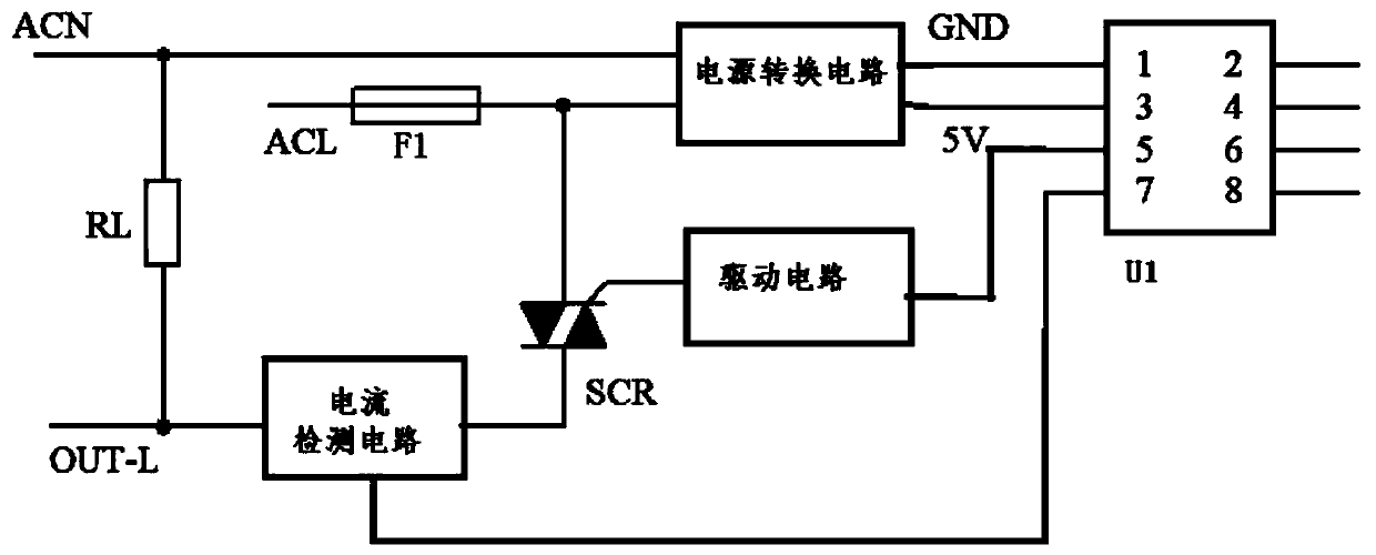
[0030] The structure of the electric kettle is as follows: figure 1 shown. The improvement of the present invention is that the control circuit board 21 in the base 1 adds an overload protection function to the heating control circuit on the control circuit board 21, so that the base of the heating pot can be used in conjunction with pot bodies with different heating powers without There is a danger of f...


PUM


Abstract

The invention discloses an electric kettle, and a heating control circuit and a heating control method for the electric kettle. The heating control circuit comprises: a silicon controlled rectifier which is connected with a heating disc of the electric kettle in series; a current detection circuit, which is connected with the heating disc in series and used for detecting heating current flowing through the heating disc; and a controller, which is used for acquiring heating current flowing through the heating disc in the heating process of the heating disc, judging whether the heating current exceeds a preset current threshold value or not, sending out a preset first control signal to enable the heating disc to conduct heating according to preset heating power if not, and sending out a preset second control signal to enable the heating disc to continue heating at a power lower than the preset heating power if so. By adding overload protection, a base can be used in cooperation with kettle bodies having different heating power limits, so the similarities and reliability of the electric kettle can be improved, and the service life of the electric kettle can be prolonged.

Description

technical field [0001] The invention relates to the technical field of heating control, in particular to an electric kettle, a heating control circuit and a heating control method thereof. Background technique [0002] This section only provides background information related to the application to facilitate those skilled in the art to understand the application more thoroughly and accurately, and it is not necessarily the prior art. [0003] Such as figure 1 As shown, the electric kettle includes a base 2 and a kettle body 1 that can be separated from the base 2. The bottom of the kettle body 1 is provided with a heating plate 11 with a predetermined heating power P0 and an upper connector 12 electrically connected to the heating plate 11. Inside the base 2 Set the control circuit board 21 connected to the mains through the plug 23 and the lower connector 22 electrically connected to the control circuit board. When the kettle body 1 is placed on the base 2, the upper conne...

Claims


Application Information

Patent Timeline
Patent Type & Authority Applications(China)
IPC IPC(8): A47J27/21A47J36/24
CPCA47J27/2105A47J27/21166A47J36/2483A47J36/32
Inventor 李一峰刘子宽肖龙飞
Owner BEAR ELECTRICAL APPLIANCE CO LTD
Why Eureka
Try Eureka