
Constant-flow type low-dead-space breathing machine

A dead space and ventilator technology, applied in the field of medical devices, can solve the problems of excessive mechanical dead space and reduce mechanical dead space, and achieve the effect of reducing cross infection, reducing dead space and simple structure

Pending Publication Date: 2020-08-04
孙志华 +1
View PDF0 Cites 0 Cited by
  • Summary
  • Abstract
  • Description
  • Claims
  • Application Information

AI Technical Summary

Problems solved by technology

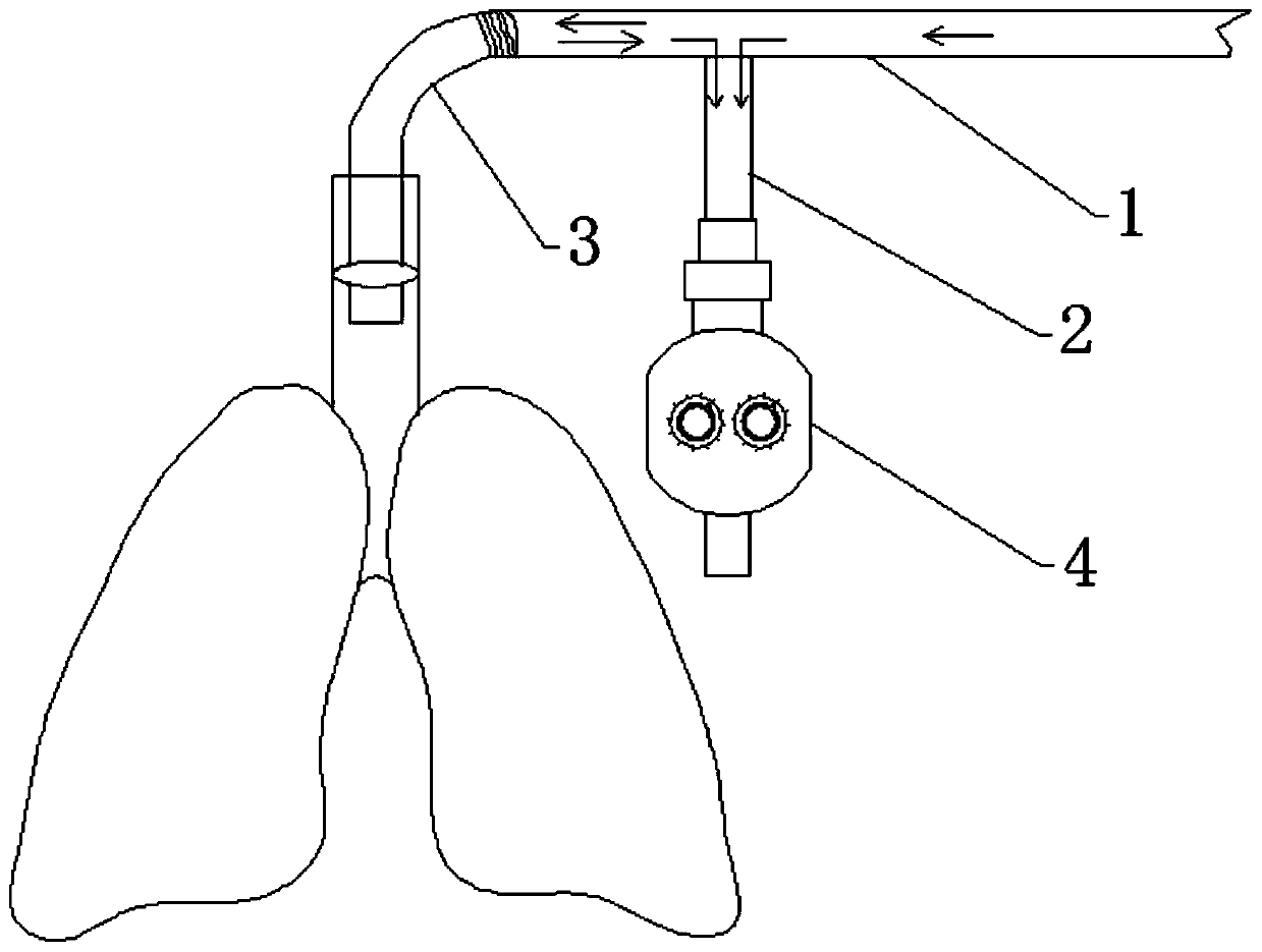
[0007] The present invention provides a constant-flow low dead space ventilator, which is a constant-flow controlled ventilator, and aims to overcome many deficiencies in existing bellows-type artificial lung pressurized and controlled breathing ventilators. Simple structure, portable, low cost and low requirements for oxygen supply equipment, especially can greatly reduce the mechanical dead space and avoid a series of problems caused by relatively large mechanical dead space

Method used


Image

  • Constant-flow type low-dead-space breathing machine
  • Constant-flow type low-dead-space breathing machine
  • Constant-flow type low-dead-space breathing machine

Examples


Embodiment Construction

[0042] The principles and features of the present invention will be described below with reference to the accompanying drawings and specific embodiments. The examples cited are only used to explain the present invention and not to limit the scope of the present invention.

[0043] In the description of the present invention, if terms such as “upper”, “lower”, “left”, “right”, “top”, “bottom”, “inner” and “outer” are used to indicate orientation, the The orientation or positional relationship is based on the orientation or positional relationship shown in the drawings, and is only for the convenience of describing the present invention and simplifying the description, rather than indicating or implying that the device or element referred to must have a specific orientation, be constructed in a specific orientation, and Therefore, it cannot be understood as a limitation of the present invention.

[0044] Such as Figure 1 to 6 As shown, the present invention provides a constant flow...


PUM


Abstract

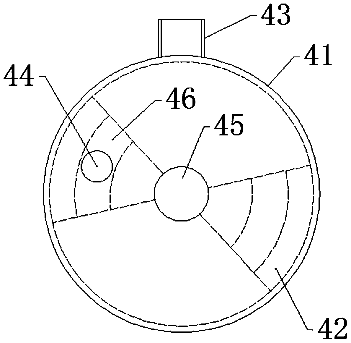
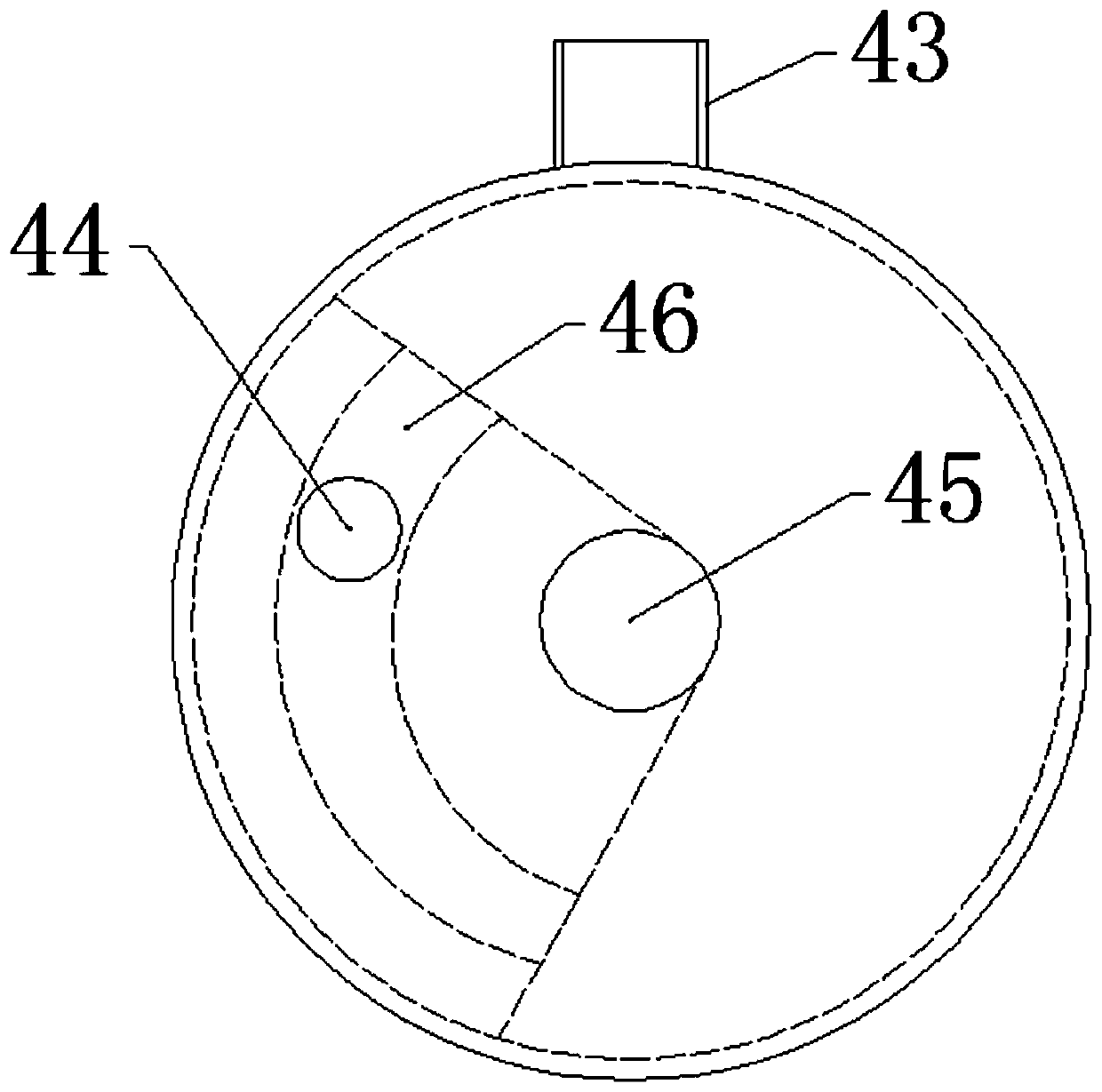
The invention provides a constant-flow type low-dead-space breathing machine which comprises a three-way pipe formed by connecting an air inlet pipe and an air outlet pipe; one end of the air inlet pipe is communicated with a tracheal catheter, and the other end of the air inlet pipe is communicated with an oxygen supply pipeline of a constant-flow oxygen supply mechanism; a connector communicatedwith the inlet end of an exhaust pipe is arranged on the pipe wall of the end, close to the tracheal catheter, of the air inlet pipe; the outlet end of the exhaust pipe is connected with a breathingcontrol mechanism; and the breathing control mechanism can circularly and alternately open and close the outlet end according to the set time proportion so as to ventilate the lung of a patient or exhaust air out of the lung. The breathing machine has the advantage that the defect that an existing breathing machine is difficult to quickly and massively equip or flexibly transfer in a temporarily-arranged mobile cabin hospital or emergency treatment center and a ward due to the characteristics of complex structure, high hardware requirement, high manufacturing cost, difficulty in moving and thelike is overcome; the breathing machine is simple in structure, portable, low in manufacturing cost and low in requirement for oxygen supply equipment, and meanwhile the problem that a mechanical dead space of an existing breathing machine is too large and cross infection exists can be solved.

Description

Technical field [0001] The invention belongs to the field of medical equipment, and specifically relates to a constant-flow type low-ineffective cavity ventilator. Background technique [0002] At present, commonly used ventilators or anesthesia machines are mostly controlled by a bellows-type artificial lung compression. Although they have many functions and ventilation modes, they have high requirements on physical hardware, often complicated designs, high cost and unfavorable transfer use. At present, due to high economic costs, difficult transfers, complicated use procedures, etc., in most hospitals, not all clinical departments and wards are equipped with ventilators. As a result, when emergency rescue of critically ill patients in the ward requires assisted breathing, tracheal intubation is required. After that, the oxygen supply tube in the center of the ward is still used to connect the simple breathing ball to manually assist breathing. Manual assisted breathing and ches...

Claims


Application Information

Patent Timeline
Patent Type & Authority Applications(China)
IPC IPC(8): A61M16/00A61M16/20
CPCA61M16/0003A61M16/0009A61M16/202A61M2016/0027
Inventor 孙志华贺争光陈溪吴义涛冯飙徐霞董茹
Owner 孙志华
Learn More