
Heating control mechanism based on Internet of Things

A control mechanism, the technology of the Internet of Things, applied in the field of the Internet of Things, can solve problems such as the inability to adjust the heating condition, and achieve the effect of avoiding insufficient heating and saving resources

Active Publication Date: 2020-08-04
济南工达智能机电有限公司
View PDF6 Cites 0 Cited by
  • Summary
  • Abstract
  • Description
  • Claims
  • Application Information

AI Technical Summary

Problems solved by technology

However, this patent still has certain technical defects. This patent cannot comprehensively adjust the environment and the heating conditions of each household, and the electric touch adjustment equipment related to the through hole

Method used


Image

  • Heating control mechanism based on Internet of Things
  • Heating control mechanism based on Internet of Things
  • Heating control mechanism based on Internet of Things

Examples


Embodiment 1

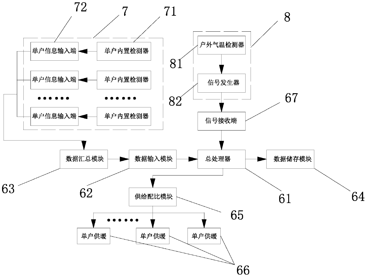
[0026] see Figure 1~3 , a heating control mechanism based on the Internet of Things, the heating control mechanism also includes a user data terminal 7, an environmental monitoring terminal 8, a general processor 61 and a supply ratio module 65, and the user data terminal 7 includes several single household built-in Monitor 71, the information entry end of described single household built-in monitor 71 is all provided with single household information input end 72, and the data output end of described single household information input end 72 is all connected with data summary module 63, and described data summary The information output end of module 63 is connected with data input module 62, and described data input module 62 is connected with the information receiving end of total processor 61 again, and described environmental monitoring end 8 comprises outdoor air temperature detector 81 and signal generator 82, The signal generator 82 is electrically connected to the sig...

Embodiment 2

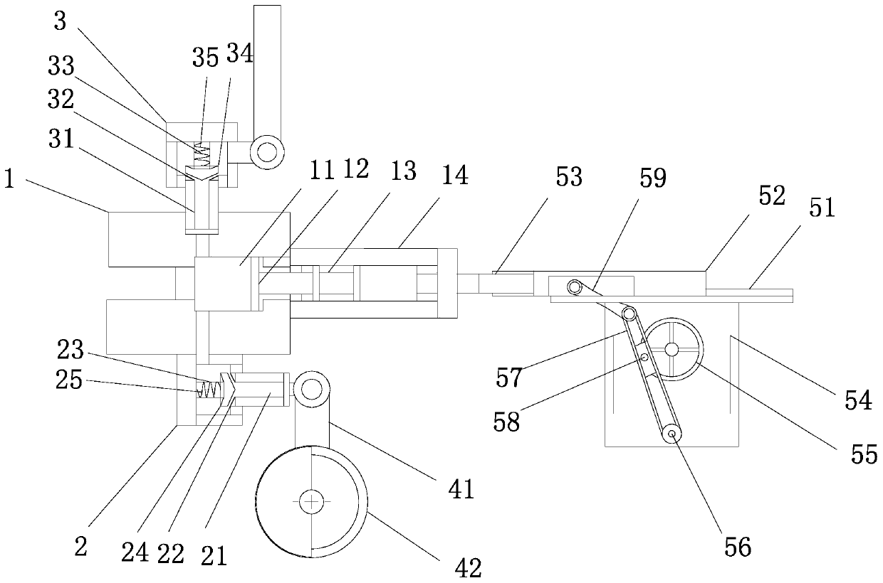
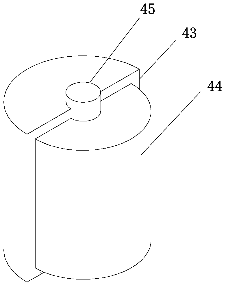
[0030] see Figure 1~3, this embodiment serves as a further optimization of the first embodiment, on the basis of which, with regard to the heating adjustment of each household, this application designs two adjustment situations. The air supply end of the air supply chamber 1 is also provided with an air supply pipeline 41, and a flow control valve 42 is installed on the air supply pipeline 41, and a flow control column 44 is arranged inside the flow control valve 42, and the flow control column 44 is arranged inside the flow control valve 42. An outer resistance sleeve 43 is installed on the flow column 44 via a central rotating shaft 45 . One is the flow regulating mechanism, which is a relatively popular prior art. The outer resistance sleeve 43 at the bottom of the electric control mechanism rotates to adjust the supply volume by adjusting the space for the airflow to flow. However, there are certain defects in this mechanism. The flow control valve 42 itself does not con...


PUM


Abstract

The invention relates to the technical field of the Internet of Things, in particular to a heating control mechanism based on the Internet of Things. The heating control mechanism comprises a user data end, an environment monitoring end, a main processor and a supply proportioning module, the user data end comprises a plurality of single-family built-in monitors, the information input ends of thesingle-family built-in monitors are provided with single-family information input ends, the data output ends of the single-user information input ends are connected with a data summarizing module, theinformation output end of the data summarizing module is connected with a data input module, the data input module is connected with the information receiving end of the main processor, the environment monitoring end comprises an outdoor air temperature detector and a signal generator, the signal generator is in electric signal connection with a signal receiving end of the main processor, the supply proportioning module is connected with an information output end of the main processor, and the supply proportioning module is used for correspondingly connecting the information output end to thesingle-family heating modules. Weather conditions are used as the minimum heating limit, and the indoor temperature condition of each house is combined for adjusting heating.

Description

technical field [0001] The invention relates to the technical field of the Internet of Things, in particular to a heating control mechanism based on the Internet of Things. Background technique [0002] In northern areas where heating is provided in winter, each community has a secondary supply station for heating. A heating company has set up many secondary supply stations. Currently, residents in a community are charged for heating in winter according to their living area, and residents pay according to their area. Finally, if the heating is not hot or the room temperature is low, they will report the problem to the community. If the community does not take measures, the residents will report the problem to their superiors, such as calling the mayor’s hotline. The level station will increase the supply of hot water to increase the temperature of the resident's room. But a more common phenomenon is that the heating temperature in the community is too high, and the resident...

Claims


Application Information

Patent Timeline
IPC IPC(8): F24D19/10F04B39/00F04B39/10
CPCF24D19/1009F24D19/1015F04B39/00F04B39/0005F04B39/0022F04B39/10F24D2220/02F24D2220/042
Inventor 郑善义
Owner 济南工达智能机电有限公司
Learn More