Screen beneath camera attaching and assembling equipment

A technology for assembling equipment and cameras, applied in mechanical equipment, packaging, material gluing, etc., can solve the problem of not eliminating the position on the camera screen film

Pending Publication Date: 2020-08-07
SHENZHEN XINSANLI AUTOMATION EQUIP
View PDF0 Cites 18 Cited by
  • Summary
  • Abstract
  • Description
  • Claims
  • Application Information

AI Technical Summary

Problems solved by technology

In the existing technology, the loading and unloading of mobile phone parts is mostly completed in a semi-manual state. In order to increase the proportion of the mobile phone screen and expand the screen film of the mobile phone to

Method used


Image

  • Screen beneath camera attaching and assembling equipment
  • Screen beneath camera attaching and assembling equipment
  • Screen beneath camera attaching and assembling equipment

Examples


Embodiment 1

[0115] Embodiment 1: the concrete structure of the present invention is as follows:

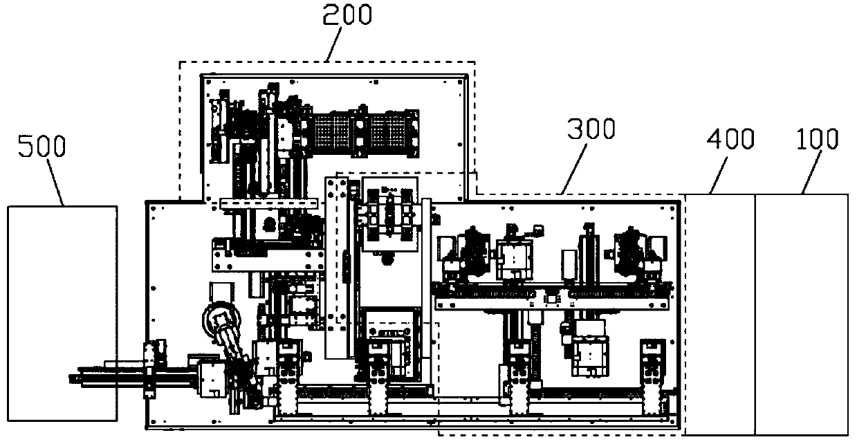
[0116] Please refer to the attached figure 1 , an under-display camera fitting and assembling device of the present invention includes a mobile phone screen loading device 500, and an organic platform is arranged on the adjacent side of the mobile phone screen feeding device 500, and is characterized in that the under-screen camera fitting and assembling device is also include:

[0117] The mobile phone screen retrieving manipulator is arranged on the machine table and placed on the mobile phone screen discharge station of the mobile phone screen feeding device 500, which is used to take out the mobile phone screen and send it to the cleaning tearing film area, and the cleaning tearing film area After the mobile phone screen is cleaned and torn off, it is sent to the ultrasonic cleaning area by the manipulator;

[0118] Fully automatic bonding structure of optical glue 200 [please refer to ...

Embodiment 2

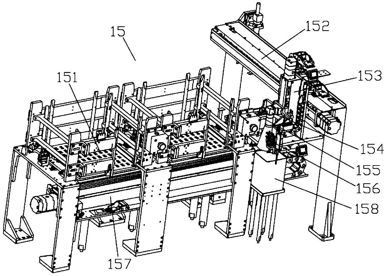
[0123] [Please refer to the attached Figure 2-8 ], the following is the specific structure of the fully automatic bonding structure 200 of optical glue:

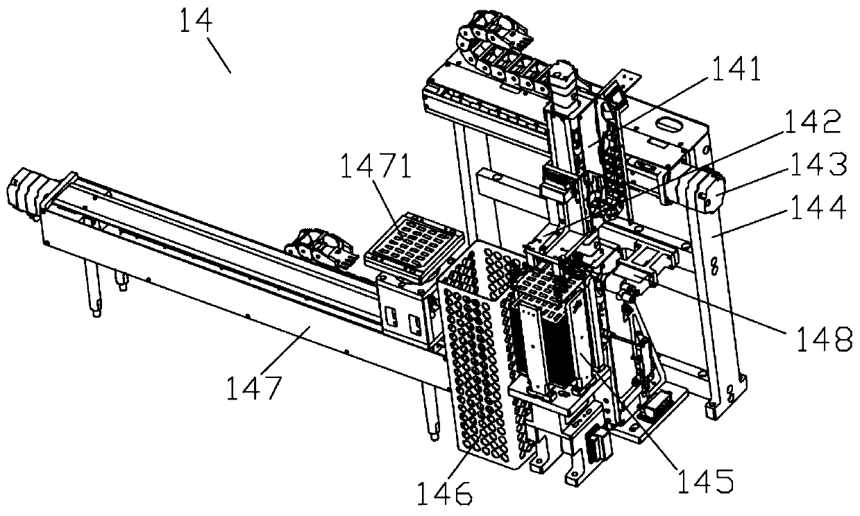
[0124] The OCA optical glue feeding area 145 includes:

[0125] first support;

[0126] Several baffles installed around the upper plane plate of the first support, the several baffles enclose the stacking cavity of OCA optical glue, and the position of each baffle can be adjusted;

[0127] The OCA turntable mechanism 147 includes a linear drive mechanism and a first adsorption device 1471 installed on the moving part of the linear drive mechanism. The power source of the linear drive mechanism is a first motor, and the driving end of the first motor is connected to the first motor. A threaded rod, which drives the first adsorption device 1471 to perform linear motion by driving the rotation of the first threaded rod;

[0128] The upper end of the first adsorption device 1471 is a platform for loading OCA optical glue. The...

Embodiment 3

[0162] The operating principle of the fully automatic laminating mechanism of the present invention is as follows:

[0163] [Please refer to the attached Figure 2-8 ], OCA optical adhesive feeding mechanism 14 is used for OCA optical adhesive feeding, and the OCA take-and-place tearing film mechanism on it first absorbs the heavy film through the suction cup, and the OCA optical adhesive is automatically separated from the light film, and then the OCA optical adhesive is transported to On the platform of the first adsorption device 1471, the negative pressure of the first adsorption device 1471 sucks the lower surface of the OCA optical glue, its adsorption force is greater than the adhesive force of the heavy film, and the Z-axis mechanism on the OCA pick-and-place tearing mechanism lifts the heavy film It is torn off and fed into the sheet film placement box 146 . The OCA turntable mechanism 147 sends the OCA optical glue without heavy film and light film into the assembly...


PUM


Abstract

The invention discloses screen beneath camera attaching and assembling equipment. Mobile phone screen feeding equipment, a mobile phone screen taking mechanical arm, an optical cement full-automatic attaching structure, a camera and mobile phone screen attaching device, a detection device and a full-automatic feeding and discharging machine are included. The mobile phone screen taking mechanical arm is used for taking out a mobile phone screen and conveying the mobile phone screen to a clean film tearing area. After the mobile phone screen is subjected to clean film tearing in the clean film tearing area, the mobile phone screen is conveyed into an ultrasonic cleaning area through the mechanical arm. The optical cement full-automatic attaching structure is used for assembling OCA optical cement and a camera. The camera and mobile phone screen attaching device is used for gluing fixing of the camera and the mobile phone screen. The detection device detects whether an assembled mobile phone screen assembly is qualified or not. The full-automatic feeding and discharging machine is used for discharging the mobile phone screen assembly and conducting disk filling. According to the screen beneath camera attaching and assembling equipment, assembling is finished at a time, secondary pollution is reduced, vision alignment is achieved, product precision and consistency are greatly improved, time is saved, the capacity is stably increased, automatic production is achieved, and the production requirements are met.

Description

technical field [0001] The invention relates to the technical field of automation equipment, in particular to an under-display camera lamination and assembly equipment. Background technique [0002] The production and assembly of 3C products is completed on the assembly line. With the advancement of technology, the automation of 3C product assembly is getting higher and higher. In the existing technology, the loading and unloading of mobile phone parts is mostly completed in a semi-manual state. In order to increase the proportion of the mobile phone screen and expand the screen film of the mobile phone to the entire panel, the position of the camera on the screen is constantly changing. Liu Haiping, water drop screen, digging screen and other technologies, these changes have not eliminated the position of the camera on the screen film. [0003] Therefore, there is an urgent need to develop an under-screen camera assembly process so that the under-screen camera product can...

Claims


Application Information

Patent Timeline
IPC IPC(8): B65G47/91B65B69/00F16B11/00B05C5/02B05C11/10
CPCB05C5/02B05C11/10B65B69/00B65G47/914F16B11/006
Inventor 李小根师利全胡争光罗东张炜贺天文刘强
Owner SHENZHEN XINSANLI AUTOMATION EQUIP
Why Eureka
Try Eureka