Filling workbench for discharging bubbles based on vibration and ensuring stability of cosmetic bottle

A cosmetic bottle and stability technology, which is applied in the field of filling workbench, can solve the problems of cosmetic spillage, waste of raw materials, and easy tilting of the bottle body, and achieve the effects of increasing linkage, ensuring uniformity, and ensuring stability

Active Publication Date: 2020-08-07
LMZ YANGZHOU HOTEL SUPPLIES
5 Cites 6 Cited by

AI-Extracted Technical Summary

Problems solved by technology

[0003] Make-up can not only make the face beautiful, but also protect the skin. As early as in the primitive society, some tribes would apply animal oil on the skin during sacrificial activities to make their complexion look healthy and shiny. This is also the earliest Skin care behavior, with the advancement of science and technology, the types and efficacy of cosmetics are increasing day by day. In the process of making cosmetics, it is necessary to fill the prepared raw materials and put them on the market for sale. Traditional cosmetics are filled During the process, there are many air bubbles in the bottle. On the one hand, the existence of air bubbles affects the appearance of the cosmetics. On the other hand, due to the pre...

Method used

Please refer to Fig. 1-6, a kind of filling workbench based on vibration discharge bubble and guarantee cosmetic bottle stability, comprises base 1, whole device is supported and stabilized, and the top of base 1 is fixedly connected with fixed plate 2 , to support the splint 3, the top of the fixed plate 2 is movably connected with a splint 3, two splints 3 are provided, the specifications of the two splints 3 are consistent and symmetrically distributed with the center line of the fixed plate 2 as a reference, the splint 3 is designed as Arc-shaped, two splints 3 are used to clamp the bottle, and the arc-shaped design makes it fit more closely with the bottle body and the clamping is more stable. A connecting rod 5 rotates, a first connecting rod 5 is movably connected to the outer side of the disk 4, and a connecting rod is movably connected between the first connecting rod 5 and the first cross bar 6, and when the first connecting rod 5 rotates, it will drive The first cross bar 6 moves up and down, and the first cross bar 6 is movably connected above the first connecting rod 5, which drives the first vertical bar 7 to move up and down, and the inside of the first cross bar 6 is movably connected with the first vertical bar 7, There are two first vertical bars 7, the specifications of the two first vertical bars 7...

Abstract

The invention relates to the technical field of cosmetics, and discloses a filling workbench for discharging bubbles based on vibration and ensuring the stability of a cosmetic bottle. The filling workbench comprises a base for supporting and stabilizing the whole device. A disc, a first connecting rod, a first cross rod, a first vertical rod, a second cross rod, a second vertical rod and a supporting plate are matched for use, so that a filling bottle is vibrated in the filling process so as to discharge bubbles in cosmetics, and oxidization of cosmetics caused by oxygen contained in the bubbles is avoided; a fixing plate, a clamping plate, a sleeve rod and a support rod are matched for use, so that in the filling process, the filling bottle is clamped, the stability of a bottle body during filling is ensured, and the problem that the bottle body is inclined to pour out cosmetics is avoided; and a rotating disc, a second rotating disc and a second connecting rod are matched for use, so that in the filling process, clamping is carried out in the vibration process, the two moving processes are linked, and the linkage of the whole device is improved.

Application Domain

Technology Topic

Image

  • Filling workbench for discharging bubbles based on vibration and ensuring stability of cosmetic bottle
  • Filling workbench for discharging bubbles based on vibration and ensuring stability of cosmetic bottle
  • Filling workbench for discharging bubbles based on vibration and ensuring stability of cosmetic bottle

Examples

  • Experimental program(1)

Example Embodiment

[0025] The technical solutions in the embodiments of the present invention will be clearly and completely described below in conjunction with the accompanying drawings in the embodiments of the present invention. Obviously, the described embodiments are only a part of the embodiments of the present invention, rather than all the embodiments. Based on the embodiments of the present invention, all other embodiments obtained by those of ordinary skill in the art without creative work shall fall within the protection scope of the present invention.
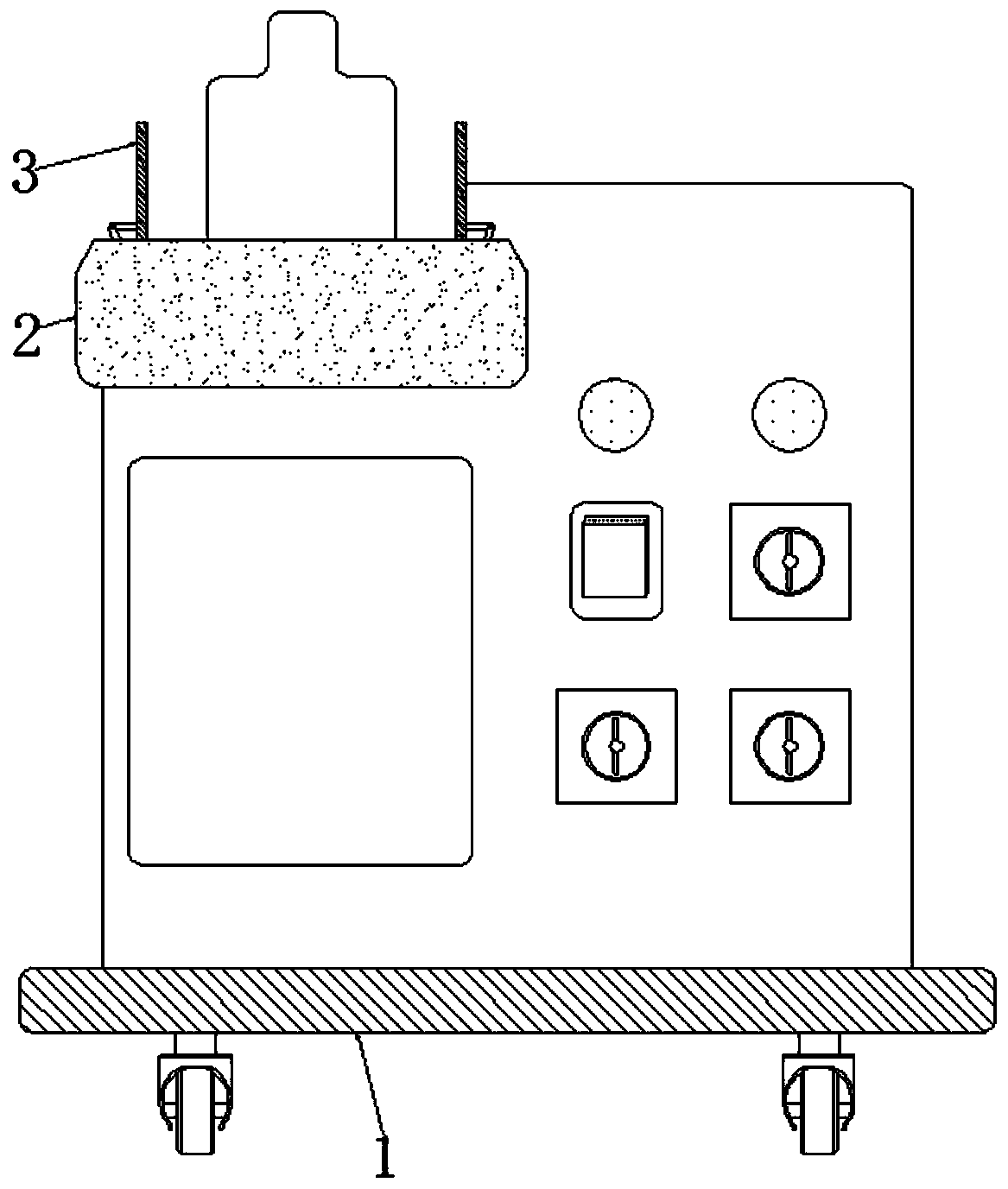
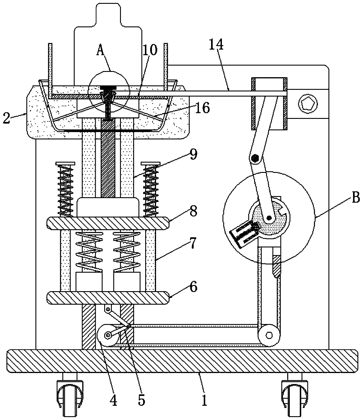
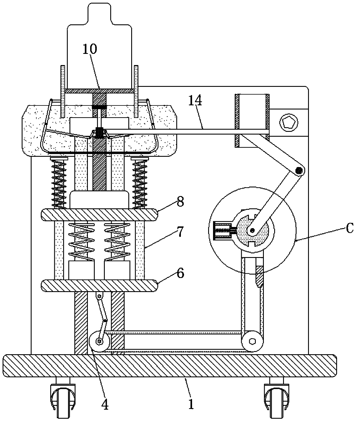
[0026] See Figure 1-6 , A filling workbench based on vibration to discharge air bubbles and ensure the stability of cosmetic bottles, including a base 1, which supports and stabilizes the entire device. The upper part of the base 1 is fixedly connected with a fixing plate 2 to support the splint 3. The fixing plate The upper part of 2 is movably connected with a splint 3, two splints 3 are provided, the specifications of the two splints 3 are the same, and they are symmetrically distributed with the center line of the fixed plate 2 as a reference. The splints 3 are designed in an arc shape, using two splints 3 pairs The holding bottle is clamped, and the arc design makes it more fit the bottle body and the clamping is more stable. The upper part of the base 1 is movably connected to the disc 4, and when the disc 4 rotates, the first connecting rod 5 is driven to rotate. A first connecting rod 5 is movably connected to the outside of 4, and a connecting rod is movably connected between the first connecting rod 5 and the first cross rod 6. When the first connecting rod 5 rotates, the first cross rod 6 will move up and down. A first crossbar 6 is movably connected to the upper part of a connecting rod 5 to drive the first vertical rod 7 to move up and down. The inside of the first crossbar 6 is movably connected with a first vertical rod 7, and the first vertical rod 7 is provided with two , The specifications of the two first vertical rods 7 are the same, and they are symmetrically distributed with the center line of the first horizontal rod 6 as a reference. A spring is movably connected between the first vertical rod 7 and the second horizontal rod 8. When the rod 6 moves upward, it will drive the first vertical rod 7 to move upward synchronously, and the design of the spring makes it possible to vibrate during the movement up and down due to elastic potential energy. The upper part of the first horizontal rod 6 is movably connected to the second horizontal rod. The inside of the second horizontal rod 8 is movably connected with a second vertical rod 9, and two second vertical rods 9 are provided. The specifications of the two second vertical rods 9 are the same, and the center line of the second horizontal rod 8 For reference to be symmetrically distributed, a spring is movably connected between the second vertical rod 9 and the first horizontal rod 6, and the second vertical rod 9 is used to support and stabilize the support plate 10, and the vibration of the second vertical rod 9 drives the support plate 10 vibrates synchronously, and the movable connection above the support plate 10 does not need to contain the bottle, thereby driving the containing bottle to vibrate, expelling the bubbles in the bottle, and making the filling more uniform.
[0027] The upper part of the second vertical rod 9 is movably connected to the support plate 10, the right side of the disc 4 is movably connected to the first turntable 11, the outer side of the first turntable 11 is provided with a limit block, and the limit block and the first turntable 11 The surface of the first turntable 11 is movably connected with the second turntable 12, and the surface of the second turntable 12 is provided with two grooves. The specifications of the two grooves are the same, and the center line of the second turntable 12 For reference to be symmetrically distributed, the size of the groove is adapted to the size of the stop block provided on the outside of the first turntable 11, when the first turntable 11 is rotated to engage with the second turntable 12, thereby driving the second turntable 12 rotates synchronously. The back of the first turntable 11 is provided with a fixed rod, and the back of the second turntable 12 is fixedly connected with a fixed block. When the first turntable 11 rotates to contact the fixed block, the limit block in the first turntable 11 Return to the original position, so finally when the first turntable 11 rotates, the second turntable 12 will be driven to rotate intermittently. The surface of the second turntable 12 is movably connected with the second connecting rod 13, which will drive when the second turntable 12 rotates. The second link 13 swings synchronously. The third link 14 is movably connected to the outside of the second link 13, and the second link 13 and the third link 14 are movably connected by the link, so the third link is finally driven The rod 14 moves up and down intermittently. The left side of the third link 14 is movably connected to the sleeve rod 15. When the third link 14 moves down, the sleeve rod 15 will be driven to move synchronously. The size of the fixed rod and the size of the sleeve rod 15 are adapted to each other. The two sides of the sleeve rod 15 are provided with connecting rods that are movably connected with the support rod 16, so that the sleeve rod 15 moves along the fixed rod to ensure the stability during movement. The outer side of the sleeve rod 15 is movably connected to the support rods 16. Two support rods 16 are designed. The specifications of the two support rods 16 are the same, and they are symmetrically distributed with the center line of the sleeve rod 15 as a reference, thereby driving the two splints 3 Intermittent clamping to ensure the stability of the bottle during the filling and shaking process.
[0028] Working principle: By movably connecting the output shaft of the motor with the disc 4, the disc 4 is driven to rotate. The outer side of the disc 4 is provided with a first connecting rod 5, so it will drive the first connecting rod 5 to rotate synchronously. A connecting rod is movably connected between the connecting rod 5 and the first cross rod 6, when the first connecting rod 5 rotates, the first cross rod 6 will move up and down, and the second cross rod 8 is movably connected above the first cross rod 6 , It will drive the second horizontal rod 8 to move up and down synchronously, and the inside of the first horizontal rod 6 and the first horizontal rod 6 are movably connected with the first vertical rod 7 and the second vertical rod 9, and the first vertical rod 7 and The outer side of the second vertical rod 9 is movably connected with a plastic spring, so when the first horizontal rod 6 moves up and down, it will vibrate. The upper end of the second vertical rod 9 is movably connected with a support plate 10, so it will eventually drive the support plate 10 vibrates up and down, and a bottle is placed above the support plate 10, so the bottle is finally driven to vibrate up and down, so as to shake out the bubbles in the filled cosmetics.
[0029] Please refer to the above structure and process Figure 2-3.
[0030] At the same time, another disk 4 is movably connected to the right side of the disk 4, and the two disks 4 are movably connected by a belt, so the two disks 4 rotate synchronously, and the other disk 4 is connected to the first turntable. 11 is movably connected by a belt, so it will drive the first turntable 11 to rotate synchronously. A limit block is arranged on the outside of the first turntable 11, and a plastic spring is movably connected between the limit block and the first turntable 11. The second turntable 12 is movably connected to the surface. The surface of the second turntable 12 is provided with two grooves. The specifications of the two grooves are the same, and they are distributed symmetrically with the center line of the second turntable 12 as a reference. The size of the stop block provided on the outside of the first turntable 11 is adapted to each other, so when the stop block in the first turntable 11 rotates to contact with the groove inside the second turntable 12, the first turntable 11 and the second turntable 11 The turntables 12 are clamped with each other to drive the second turntable 12 to rotate synchronously. The back of the first turntable 11 is provided with a fixed rod, and the back of the second turntable 12 is fixedly connected with a fixed block. When the first turntable 11 rotates to contact the fixed block After that, the stop block in the first turntable 11 returns to the original position, so finally when the first turntable 11 rotates, the second turntable 12 will be driven to rotate intermittently, and the second connecting rod 13 is provided on the outside of the second turntable 12, In addition, the second link 13 and the third link 14 are movably connected by a connecting rod, so the third link 14 will eventually be driven to move up and down intermittently, and the sleeve rod 15 is movably connected to the left side of the third link 14, so The sleeve rod 15 is driven to move synchronously up and down intermittently. There are support rods 16 on both sides of the sleeve rod 15. When the sleeve rod 15 moves down, the opening angle of the support rod 16 will be changed. There are two special shapes on the outside of the support rod 16. The rod is movably connected with the splint 3. When the opening angle of the support rod 16 changes, the two splints 3 will eventually be pushed to move inward at the same time, thereby clamping the filling bottle. Similarly, when the sleeve rod 15 moves upward, it will The splint 3 is driven to move to the outside, thereby loosening the filling bottle, and filling is completed at this time.
[0031] Please refer to the above structure and process Figure 2-6.
[0032] Although the embodiments of the present invention have been shown and described, those of ordinary skill in the art can understand that various changes, modifications, and substitutions can be made to these embodiments without departing from the principle and spirit of the present invention. And variations, the scope of the present invention is defined by the appended claims and their equivalents.

PUM

no PUM

Description & Claims & Application Information

We can also present the details of the Description, Claims and Application information to help users get a comprehensive understanding of the technical details of the patent, such as background art, summary of invention, brief description of drawings, description of embodiments, and other original content. On the other hand, users can also determine the specific scope of protection of the technology through the list of claims; as well as understand the changes in the life cycle of the technology with the presentation of the patent timeline. Login to view more.

Similar technology patents

Classification and recommendation of technical efficacy words

  • Guaranteed uniformity
  • Guaranteed stability

Visual soil freeze-thawing process test apparatus

Owner:NORTHWEST INST OF ECO-ENVIRONMENT & RESOURCES CAS

Preparation method of metal-organic framework compound with hierarchical pore structure

InactiveCN104151336AGuaranteed stabilityMaintain crystal shapeCopper organic compoundsZinc organic compoundsSolventIon
Owner:FUDAN UNIV
Why Eureka
Try Eureka