Flotation cabinet device with multi-stage flow guide and overflow structural form

A structure and cabinet technology, applied in the field of flotation cabinet devices, can solve the problems of heavy equipment weight, eutrophication pollution of water bodies, long cleaning time, etc. Effect

Active Publication Date: 2020-08-07
WUHAN SECOND SHIP DESIGN & RES INST
View PDF5 Cites 0 Cited by
  • Summary
  • Abstract
  • Description
  • Claims
  • Application Information

AI Technical Summary

Problems solved by technology

[0003] Due to the interactive influence of environmental conditions such as temperature, humidity and swing, residence time, operation mode, discharge water quality and water quantity, biofilm method is often impossible to continuously meet the discharge standard requirements, resulting in re-eutrophic pollution of water bodies; secondly , the process is long and the equipment takes up a lot of space
In addition, this method needs to use membrane modules to filter sewage, which is expensive and takes a long time to clean, and the cost of use is relatively high
[0004] The electrochemical method mainly relies on the discharge between the electrode plates to electrolyze the sewage. The electrolysis process requires a large current and consumes too much energy. Secondly, the electrode plates are expensive and require a high initial investment. In addition, because electrolysis requires many containers , the weight of the equipment is heavy and explosive gas will be generated during the electrolysis process, therefore, the safety requirements for equipment operation management are also very high

Method used


Image

  • Flotation cabinet device with multi-stage flow guide and overflow structural form
  • Flotation cabinet device with multi-stage flow guide and overflow structural form
  • Flotation cabinet device with multi-stage flow guide and overflow structural form

Examples


Embodiment Construction

[0026] The present invention will be further described below in conjunction with the accompanying drawings and examples, but these examples should not be construed as limiting the present invention.

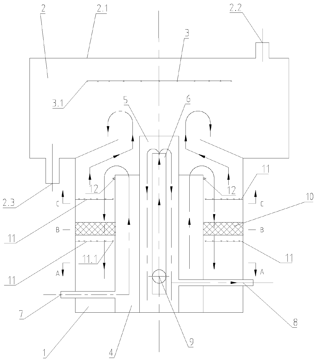
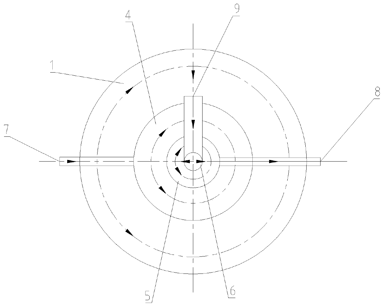
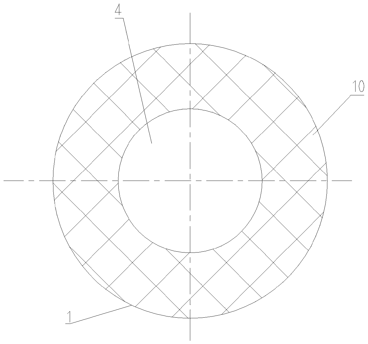
[0027] A flotation cabinet device with multi-stage diversion and overflow structure as shown in the figure includes a flotation cabinet 1 and a solid matter collection chamber 2, the flotation cabinet 1 is a circular container, and the flotation cabinet The top of 1 is conical and has an opening in the central part. The solid matter collection chamber 2 is a circular container with an opening at the bottom. The solid matter collection chamber 2 is coaxially connected with the flotation cabinet 1 and makes the The conical top is located in the inner cavity of the solid matter collection chamber 2. The solid matter collection chamber 2 includes a cover 2.1, an air vent 2.2 and a solid matter discharge port 2.3. The upper part of the solid matter collection chamber 2 is provided with...


PUM


Abstract

The invention relates to a flotation cabinet device with a multi-stage flow guide and overflow structure form. The flotation cabinet device comprises a flotation cabinet body and a solid matter collecting chamber, wherein the top of the flotation cabinet body is conical and is provided with an opening; an opening is formed in the bottom of the solid matter collecting chamber; the conical top of the flotation cabinet body is positioned in the inner cavity of the solid matter collecting chamber; a flushing water pipe is arranged in the solid matter collecting chamber; a first-stage flow guide groove, a second-stage flow guide groove and a third-stage flow guide groove are sleeved in the flotation cabinet body stage by stage and are coaxially arranged with the flotation cabinet body; the topof a primary diversion trench is open and is positioned below the lower edge of the conical top of the flotation cabinet body; a domestic sewage inlet pipe is communicated with the first-stage flow guide groove, a clear water outlet pipe is communicated with the second-stage flow guide groove, the two ends of the supernatant inlet pipe are connected with the flotation cabinet body and the third-stage flow guide groove respectively, and a fixed bed reactor, a radial compressed air straight pipe and an annular compressed air pipe are further arranged in the flotation cabinet body. The device iscompact in arrangement, convenient to use, reliable in operation, high in treatment capacity and low in energy consumption.

Description

technical field [0001] The invention relates to the treatment of ship's domestic sewage, in particular to a flotation cabinet device in the form of multi-stage diversion and overflow structure. Background technique [0002] Domestic sewage treatment is a necessary condition for the continuous and normal operation of ships and offshore platforms. Currently, domestic sewage from ships and offshore platforms is usually treated by biofilm or electrochemical methods. [0003] Due to the interactive influence of environmental conditions such as temperature, humidity and swing, residence time, operation mode, discharge water quality and water quantity, biofilm method is often impossible to continuously meet the discharge standard requirements, resulting in re-eutrophic pollution of water bodies; secondly , the method has a long process flow and takes up a lot of equipment space. In addition, this method requires the use of membrane modules to filter sewage. The membrane modules ar...

Claims


Application Information

Patent Timeline
Patent Type & Authority Applications(China)
IPC IPC(8): C02F1/24B63J4/00
CPCC02F1/24B63J4/006C02F2201/002C02F2201/003C02F2201/008C02F2303/14
Inventor 温恩龙杨旺黄琨鲜春媚廖聪方震桂霆
Owner WUHAN SECOND SHIP DESIGN & RES INST
Why Eureka
Try Eureka