Copper plating production line for producing printing rollers

A production line and printing roller technology, which is applied in the field of roller body electroplating equipment, can solve the problems of roller body surface scratches, roll body volume, and roller body collision, etc., to achieve the effect of improving work efficiency, reducing work burden, and ensuring quality

Active Publication Date: 2020-08-07
太仓市施美电镀有限公司
View PDF8 Cites 5 Cited by
  • Summary
  • Abstract
  • Description
  • Claims
  • Application Information

AI Technical Summary

Problems solved by technology

[0004] Although the above technical solution can realize the automatic clamping of the central axis at both ends of the roller body, due to the large volume of the roller body, manual loading and unloading is still required in the electroplating process, so in the process of electroplating the roller body , it is necessary to manually carry the roller body continuously, which not only increases the workload of the workers, but also may cause the collision of the roller body during the handling process, causing scratches on the surface of the roller body, which will affect the effect and quality of the electroplating roller. quality

Method used


Image

  • Copper plating production line for producing printing rollers
  • Copper plating production line for producing printing rollers
  • Copper plating production line for producing printing rollers

Examples


Embodiment Construction

[0042] The present invention will be described in further detail below in conjunction with the accompanying drawings.

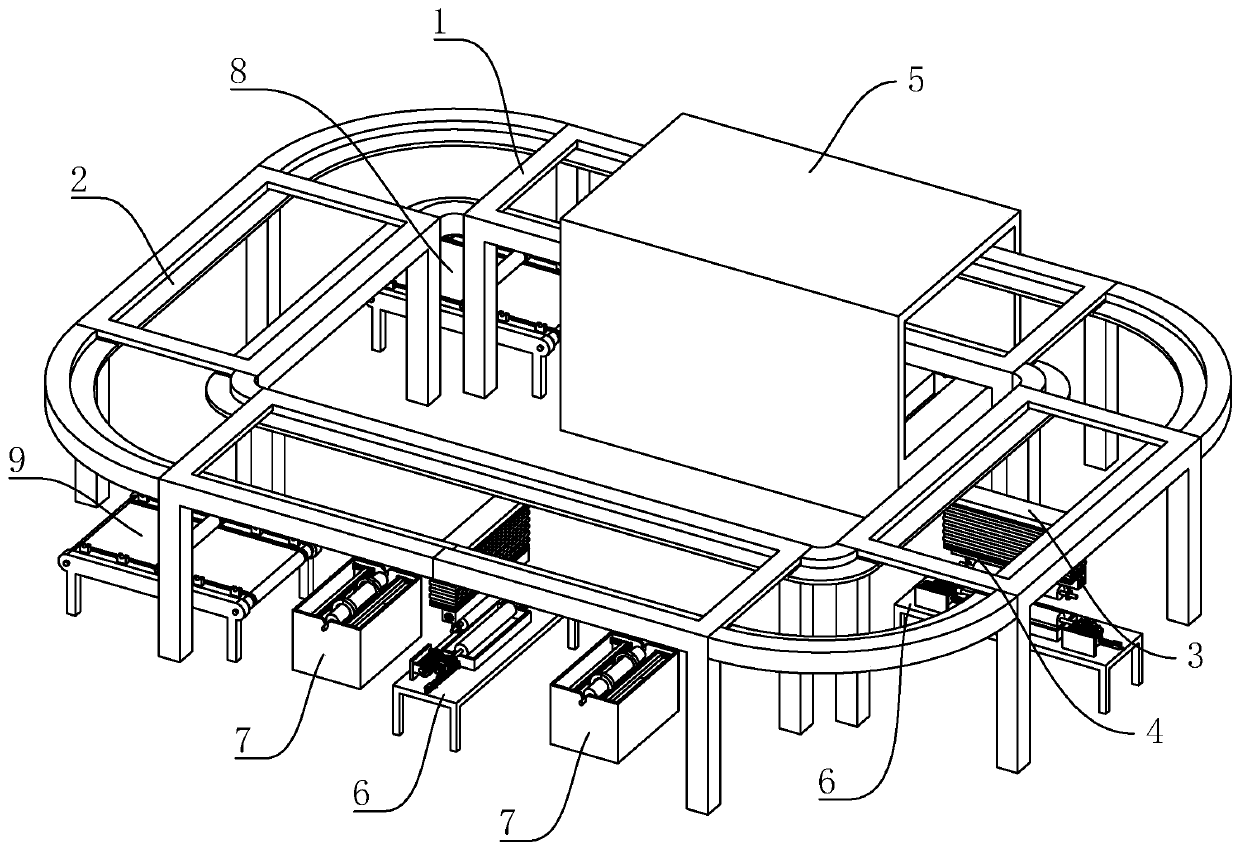
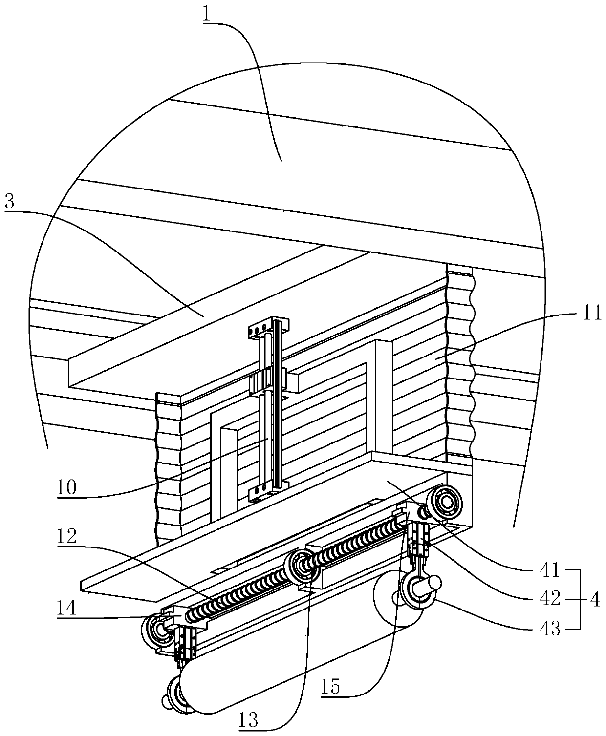
[0043] refer to figure 1 , which is a copper plating production line for producing printing rollers disclosed by the present invention, comprising a support frame 1, on which a circular double-speed chain 2 is arranged, and the circular double-speed chain 2 is arranged in a rectangular shape, connected on the circular double-speed chain 2 There is a horizontal mobile frame 3, and a vertical mobile frame 4 is connected with sliding on the horizontal mobile frame 3. refer to image 3 The vertical moving frame 4 includes a connecting plate 41, a pneumatic finger 42 connected to the lower end of the connecting plate 41, and a roller body limiting ring 43 fixedly connected to the output end of the pneumatic finger 42. The end shaft plays the role of clamping. When the roller body limit ring 43 clamps the roller body, the horizontal moving frame 3 will move under...


PUM


Abstract

The invention relates to a copper plating production line for producing printing rollers. The copper plating production line for producing the printing rollers includes a support frame; a circular double speed chain is arranged on the support frame; a horizontal moving frame is connected to the circular double speed chain; a vertical moving frame is slidingly connected to the horizontal moving frame; the vertical moving frame includes a connecting plate, a pneumatic finger connected to the lower end of the connecting plate, and a roller body limit ring fixedly connected to the output end of the pneumatic finger; a pretreatment working section, an electroplating section and a cleaning section are arranged under the support frame in order along the moving direction of the roller body; and aloading device and an unloading device are arranged between the pretreatment working section and the cleaning section. According to the invention, when performing an electroplating operation on the roller body, the circular double speed chain can drive the horizontal moving frame and the vertical moving frame to move, and the roller body can be driven to move automatically during the movement process of the horizontal moving frame and the vertical moving frame, which cannot cause collision between the roller body and the machine body; and therefore, the relatively stable movement of the rollerbody can be ensured, and the quality of the roller body electroplating can be ensured.

Description

technical field [0001] The invention relates to the technical field of roller body electroplating equipment, in particular to a copper plating production line for producing embossing rollers. Background technique [0002] The printing roller is also called roller printing. It is a printing process that continuously transfers the printing paste or pattern to the surface of the fabric through the pattern or pattern engraved on the metal roller through the continuous rotation of the machine. At the same time, the printing roller can also be used for Production of embossed leather and wood products. Due to the low hardness of copper, it is necessary to electroplate copper on the roller body before engraving the embossing roller, and then electroplate chrome on the roller body after engraving the copper coating, so as to ensure the strength of the embossing roller and improve the strength of the embossing roller. quality. [0003] When electroplating the embossing roller, it is...

Claims


Application Information

Patent Timeline
Patent Type & Authority Applications(China)
IPC IPC(8): C25D19/00C25D21/10C25D17/06C25D21/08
CPCC25D17/00C25D21/10C25D17/06C25D21/08
Inventor 张福全曲跃威陈少功
Owner 太仓市施美电镀有限公司
Why Eureka
Try Eureka