
Multi-way control valve for hydraulic excavator

A multi-way control valve and oil circuit technology, which is applied to mechanically driven excavators/dredgers, earth movers/shovels, construction, etc., can solve the inconvenient adjustment of compound actions, large pressure loss of parallel oil circuits, Inability to give full play to performance and other problems, to achieve the effect of light valve body, reduced fuel consumption and improved operating performance

Inactive Publication Date: 2020-08-07
SHANDONG CHANGLIN MACHINERY GRP
View PDF0 Cites 1 Cited by
  • Summary
  • Abstract
  • Description
  • Claims
  • Application Information

AI Technical Summary

Problems solved by technology

Excavator multi-way valves in the prior art have a large amount of deformation when the valve body is connected, the structure of the valve core is complicated, the regenerative ability of the stick is poor, and the processing is difficult and the manufacturability is poor.
The pressure loss of the parallel oil circuit is large, which increases the fuel consumption
It is inconvenient to adjust the compound action, and the performance of each actuator cannot be fully exerted
Makes the maneuverability of the excavator poor, affecting work efficiency

Method used


Image

  • Multi-way control valve for hydraulic excavator
  • Multi-way control valve for hydraulic excavator
  • Multi-way control valve for hydraulic excavator

Examples


Embodiment Construction

[0090] Below in conjunction with accompanying drawing, structural principle and working principle of the present invention are specifically described:

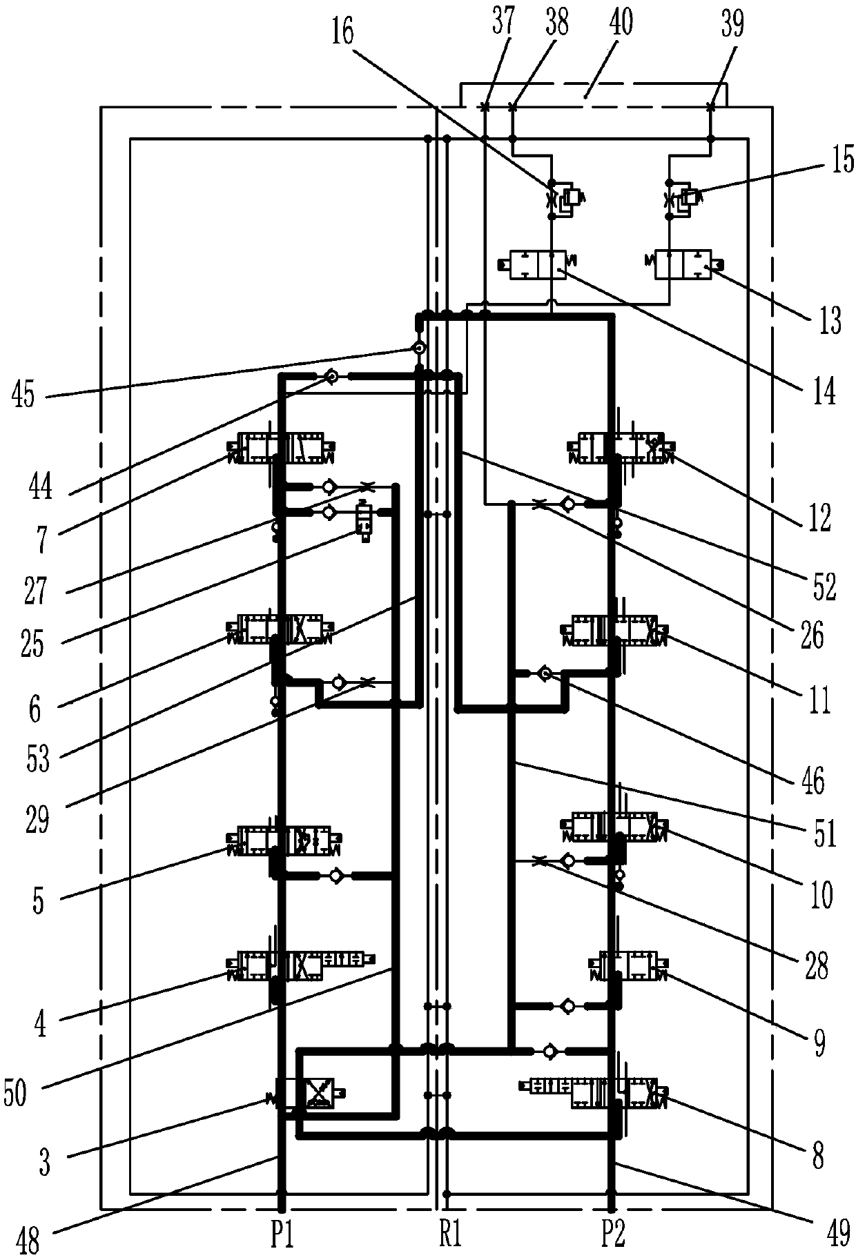
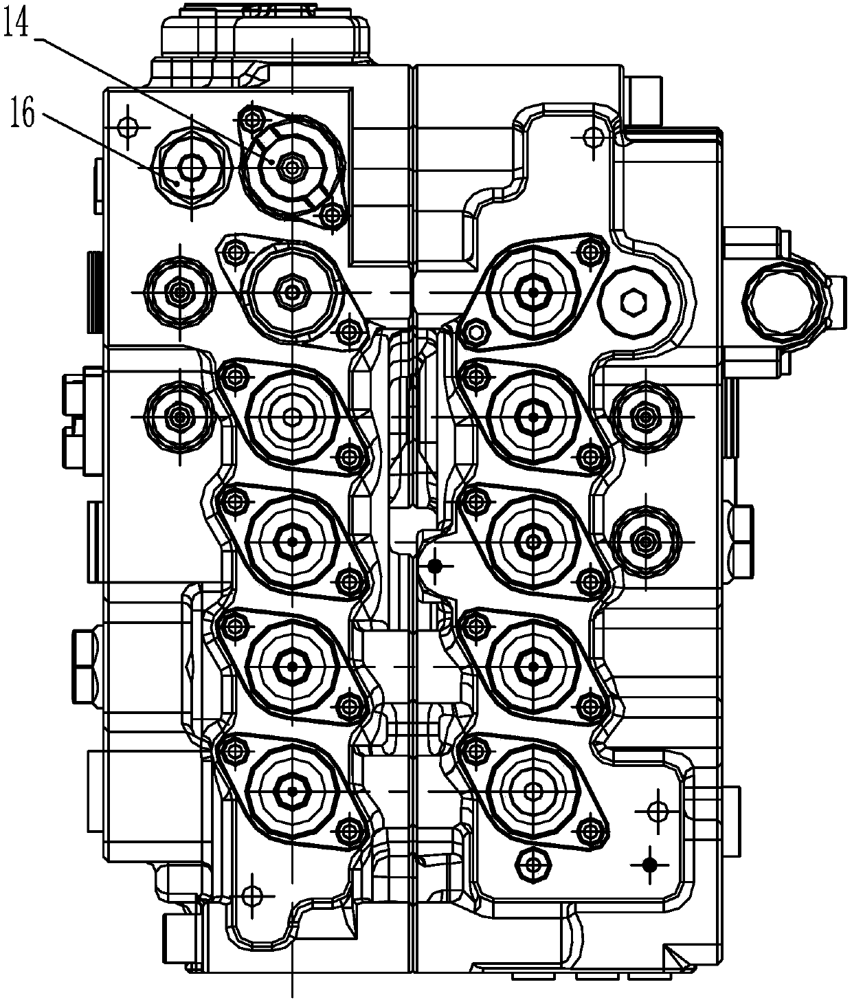
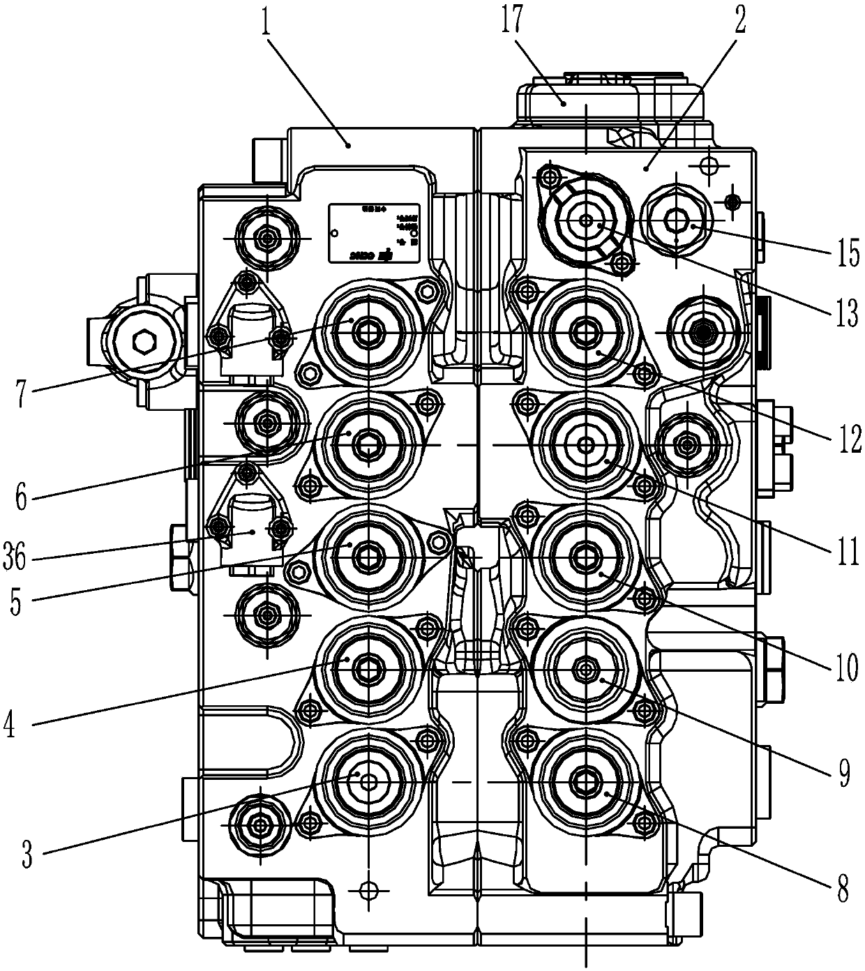
[0091] see figure 1 , figure 1 It is a working principle diagram of the present invention. The multi-way control valve used for hydraulic excavators in the present invention includes a left valve body 1, a right valve body 2, and a left traveling valve coupling 4 and a right traveling valve coupling 8 arranged in the left valve body 1 and the right valve body 2 , the first boom valve connection 5, the first stick valve connection 12, the bucket valve connection 6, the rotary valve connection 10, the front pump oil inlet P1, the rear pump oil inlet P2 and the oil return port R1, the left The travel valve connection 4, the right travel valve connection 8, the first boom valve connection 5, the first stick valve connection 12, the bucket valve connection 6, and the rotary valve connection 10 are respectively connected with the ...


PUM


Abstract

The invention discloses a multi-way control valve for a hydraulic excavator. The multi-way control valve comprises a left valve body, a right valve body, a left travelling valve coupling, a right travelling valve coupling, a first movable arm valve coupling, a first bucket rod valve coupling, a bucket valve coupling, a rotary valve coupling, a front pump oil inlet, a rear pump oil inlet and an oilreturn opening, wherein the left travelling valve coupling and the right travelling valve coupling are arranged in the left valve body and the right valve body respectively, the left travelling valvecoupling, the right travelling valve coupling, the first movable arm valve coupling, the first bucket rod valve coupling, the bucket valve coupling and the rotary valve coupling achieve traveling, movable arm, bucket rod, bucket and rotary actions through control of a pilot oil way respectively, the left traveling valve coupling, the first movable arm valve coupling and the bucket valve couplingcommunicate through a first series oil way and a first parallel oil way respectively, the first series oil way is connected with the front pump oil inlet and the first parallel oil way correspondingly, the right travelling valve coupling, the first bucket rod valve coupling and the rotary valve coupling communicate through a second series oil way and a second parallel oil way respectively, and thesecond series oil way is connected with the rear pump oil inlet and the second parallel oil way correspondingly.

Description

technical field [0001] The invention relates to a multi-way control valve for a hydraulic excavator, in particular to a multi-way control valve capable of meeting the different demands on the flow and pressure of each actuator of an 18-36 ton medium-sized hydraulic excavator. Background technique [0002] At present, domestic hydraulic excavators mainly have two kinds of oil circuit systems: the open center direct oil return six-way valve system and the closed center load sensitive pressure compensation system. Most large and medium-sized hydraulic excavators use the open center system. This hydraulic control system mainly includes a negative flow control system and a positive flow control system. Since the negative flow control system is relatively mature, and the positive flow control electronic control system is complex and expensive, most domestic hydraulic excavators use the negative flow control system. . The multi-way valve body of the excavator in the prior art has ...

Claims


Application Information

Patent Timeline
IPC IPC(8): E02F9/22E02F3/42
CPCE02F3/42E02F9/22E02F9/2217E02F9/2221E02F9/2267
Inventor 郇庆祥李合永张海洋巩秀江刘桂芳
Owner SHANDONG CHANGLIN MACHINERY GRP
Learn More